background image

1-26

1900-009-001 REV B

www.stryker.com

Return To Table of Contents

En

gli

sh

Accessories

OPERATING THE THREE-STAGE IV POLE (OPTIONAL)

 WARNING

Make sure that proper policies are applied to ensure the patient’s safety when an IV pole and/or an oxygen bottle are 
used. The patient should not be able to reach nor manipulate them.

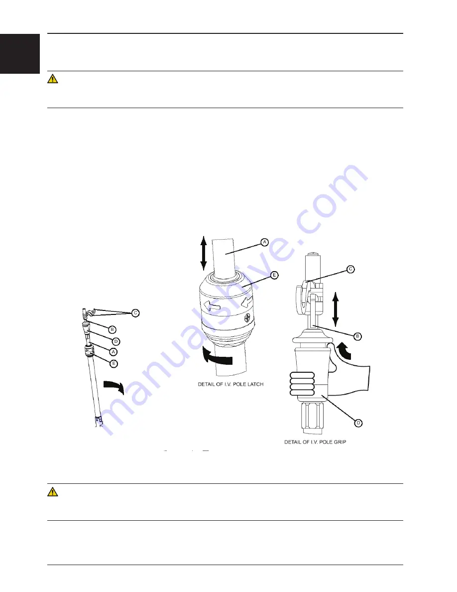
To use the three-stage IV pole, refer to Figure 15 and follow steps 1-5 below:
1.  Lift and pivot the pole from the storage position and push it down until it is locked into the receptacle.
2.  To raise the height of the pole, pull up on the first telescoping portion (A) until it locks into place at its fully raised 

position. There are no intermediary positions for this section.

3.  For a higher IV pole, pull up on the second telescoping portion (B). Release the section (B) at any desired height 

and it will lock into place. To lower the section, push up on the red part of the handle while holding the section and 
lower the section to the desired height. Release the red part of the handle to lock the section into place.

4.  Rotate the IV hangers (C) to the desired position and hang the IV bags.
5.  To store the IV pole, push up on the red portion of the grip (D) while holding onto section (B) and lower it 

completely. Turn latch (E) clockwise to lower section (A). Lift up the pole to remove it from its receptacle, fold it 
and insert the hangers into the location provided on the adjacent accessory bracket.

 CAUTION

• 

The weight of the IV bags should not exceed 40 lb (18 kg).

• 

Do not install a two or three-stage fixed IV pole at the foot end of a stretcher equipped with the scale.

Figure 15 - 3-Stage IV Pole


Summary of Contents for cub

Page 1: ...2014 10 B 0 1900 009 001 REV B www stryker com CUB Pediatric Crib REF FL19F H 190 Operations Manual Detachable Quick Reference Guide see back of manual ...

Page 2: ......

Page 3: ...uid splash Direct Current In accordance with European Directive 2002 96 EC on Waste Electrical and Electronic Equipment this symbol indicates that the product must not be disposed of as unsorted municipal waste but should be collected separately Refer to your local distributor for return and or collection systems available in your country REF Model Manufacturer Symbols ...

Page 4: ......

Page 5: ... 1 16 Raising or Lowering the Litter Optional FL19H Only 1 17 Trendelenburg Reverse Trendelenburg Optional FL19H Only 1 17 Operating the Fowler Foot Sections 1 18 Manual Fowler Positioning 1 18 Pneumatic Fowler Positioning 1 18 Foot Section Positioning 1 18 Operating the Siderails 1 19 Operating Access Doors Optional 1 19 Operating the Scale Optional 1 20 Battery Replacement 1 22 Accessories 1 23 ...

Page 6: ...structions 1 33 REMOVAL OF IODINE STAINS 1 33 Preventive Maintenance 1 34 Checklist 1 34 Recycling passport 1 35 Limited Warranty 1 36 Warranty exclusion and damage limitations 1 36 To obtain parts and service 1 36 Return Authorization 1 36 Damaged Merchandise 1 36 International Warranty Clause 1 36 CUB Crib Quick Reference Guide 1 39 Base Controls 1 41 Applying the Brakes 1 41 Raising Lowering Li...

Page 7: ...e potential serious adverse reactions and safety hazards CAUTION Alerts the reader of a potentially hazardous situation which if not avoided may result in minor or moderate injury to the user or patient or damage to the equipment or other property This includes special care necessary for the safe and effective use of the device and the care necessary to avoid damage to a device that may occur as a...

Page 8: ...an 35 inches INTENDED PART OF THE BODY The Stryker Cub Pediatric Crib is intended to support a patient while meeting safe working loads The patient can come in contact with the crib but should never be placed on the frame without a sleep surface Cub is intended to be used with a 4 in sleep surface a thicker sleep surface or overlay that offers therapeutic value The crib should be used with extra c...

Page 9: ...Reverse Trend Foot Section Angle 0 25 40 55 0 50 9 5 0 6 12 0 25 40 55 0 50 0 6 12 with manual foot prop 0 6 12 Patient Surface 29 5 in x 57 in 75 x 145 cm 29 5 in x 57 in 75 x 145 cm Caster Diameter 6 in 15 cm 5 in 13 cm Brake System Four Wheel Ring Brake System Four Locking Casters Scale Optional Capacity Patients weighing 4 lb 1 8 kg to 100 lb 54 4 kg Accuracy Perform scale measurement when uni...

Page 10: ...ing environment recommended to ensure scale precision Environmental Conditions Operation Storage and Transportation Ambient Temperature Relative Humidity Non Condensing Atmospheric Pressure Introduction 60 0 F 85 0 F 15 5 0 C 29 1 0 C 22 0 F 122 0 F 30 0 C 50 0 C 0 95 0 95 700 hPa 1060 hPa 500 hPa 1060 hPa ...

Page 11: ...EASE KNOBS SIDERAIL ACTIVATION HANDLE FOOT SECTION DRAINAGE BAG HOOK FOOT SECTION SUPPORT ARM HEAD PREMIUM ACCESSORY BRACKETS OPTIONAL OXYGEN BOTTLE RETAINING COLLAR OPTIONAL IV CADDY ARM OPTIONAL PNEUMATIC HEAD SECTION ACTIVATION LEVER UNI LOWER PEDAL OPTIONAL LITTER LIFT PEDAL OPTIONAL GROUND CHAIN BRAKE STEER PEDAL OPTIONAL SIDE AND END RAILS OPTIONAL Figure 1 Bed illustration PRODUCT ILLUSTRAT...

Page 12: ... B www stryker com Return To Table of Contents English Introduction CONTACT INFORMATION Contact Stryker Customer Service or Technical Support at 1 800 327 0770 Stryker Medical 3800 E Centre Avenue Portage Michigan 49002 USA ...

Page 13: ...he area below and around the litter To avoid falls and injury verify the rails and access doors are properly locked into position before leaving a patient unattended or after having moved a rail or an access door To avoid injury to the patient ensure the patient s extremities are clear of all moving parts before operating a rail Always ensure the rail is securely locked after moving it To avoid fa...

Page 14: ...n the scale accuracy it is recommended to zero the scale at least once a week Note that the patient must be removed from the stretcher before zeroing the scale Use only 1 5 VDC alkaline batteries The use of batteries other than the one recommended may damage the scale electronic components Remove the batteries if the scale module or the stretcher is not used for long periods Always store the IV Ca...

Page 15: ... is stabilized Next press and keep pressed during at least two seconds the Zero button A 0 0 lb kg weight should appear on the display four to ten seconds later NOTE The scale automatically shuts off after a 30 seconds of inactivity except during the Change Equipment procedure where there is a three minute delay To reactivate the scale press the Weigh On button 2 The weight reading can be displaye...

Page 16: ...Movement Verification see section 2 6 8 Optional assisted or manual Fowler operates properly LITTER MOVEMENT VERIFICATION Refer to page 1 14 1 Optional assisted or manual Fowler operates properly NOTE To raise the assisted Fowler a slight push under the top part of the Fowler is needed to start its rise to lower it push down on its top part while lifting the activation lever 2 Foot section support...

Page 17: ...Depress the center of pedal B to lower both ends of the stretcher together C Depress the side of pedal B closest to the stretcher head end to lower the head end D Depress the side of pedal B closest to the stretcher foot end to lower the foot end E Brake and Steer functions left side Steer F Steer and Brake functions right side Operation E F A A D B C D B C HEAD END RIGHT LEFT Figure 2 Base Contro...

Page 18: ...G When brakes are applied ensure all four casters are locked to ensure complete stabilization of the stretcher To engage the caster brakes press fully down on all four caster brake levers A see Figure 3 To disengage the caster brake push the opposite side of the brake lever with your foot or lift up with your toe under the brake lever see Figure 3 OPERATING THE DIRECTIONAL FIFTH WHEEL OPTIONAL WAR...

Page 19: ...the side of pedal B page 1 15 closest to the head end To lower only the foot end of the litter depress the side of pedal B page 13 closest to the foot end TRENDELENBURG REVERSE TRENDELENBURG OPTIONAL FL19H ONLY NOTE The litter height must be raised first in order to achieve a Trendelenburg position WARNING To avoid injury to the patient and or the user ensure the rails are in their highest positio...

Page 20: ...d position To flatten the Fowler hold the handle while lowering the Fowler to flat and release the support see Figure 4 PNEUMATIC FOWLER POSITIONING To raise the Fowler lift up the right or left activation lever B while lifting the Fowler to the desired postion see Figure 5 and release the lever once the desired height is achieved To lower the Fowler push down on the Fowler while lifting up the ri...

Page 21: ...ilable locking positions are crossed see Figure 6 To lower a siderail endrail grasp the handle A Activate the trigger turn handle to the left or right and guide the rail down to the desired height Return the handle back to vertical to lock the rail into desired position see Figure 6 NOTE For safety reasons side endrails automatically stop and lock at the 9 in position even if the handle is kept tu...

Page 22: ...ed or the stretcher stabilized before using the scale again see the Error Code List in the Maintenance Manual NOTE The scale does not work in continuous mode It must be activated using the Weigh On key each time a reading of the patient s weight is required B Memory Stores the result of the weighing or recalls on display the weight stored C Zero Zeroes the weight displayed on screen and the weight...

Page 23: ...nt in the stretcher press the Weigh On button The patient s weight will be displayed four to ten seconds later CAUTION To maintain the scale accuracy it is recommended to zero the scale at least once a week Note that the patient must be removed from the stretcher before zeroing the scale B STORING IN MEMORY A WEIGHT READING Press the Weigh On button to activate the scale Wait for the reading to be...

Page 24: ...T Press the Weigh On button to activate the scale A weight reading will appear on the display four to ten seconds later Press the lb kg button to change from pounds lb to kilograms kg or conversely The lb kg button can be deactivated to prevent inadvertent use of the button To do so press and hold the lb kg and Memory buttons for at least two seonds Do the same to reactivate the lb kg button BATTE...

Page 25: ...is made up of all the upper part of the stretcher including the safety end siderails the accessory brackets the drainage bag hooks the chart and monitor holders optional located under the mattress support Ensure no external object is in contact with the stretcher during a weighing or when zeroing the scale Figure 10 Standard Accessory Bracket REMOVABLE IV POLE INSTALLED NOT INCLUDED PROTECTIVE TOP...

Page 26: ...ft the IV Caddy from the storage clip 2 Pivot the IV Caddy to the desired position 3 Turn knob A counter clockwise to loosen the pole clamp C 4 Pivot the knob A away from the clamp B The clamp C may then be opened 5 Place the IV pole into the clamp B Close the clamp C around the IV pole and pivot the knob A back into position 6 Turn the knob clockwise to tighten it The IV pole is now ready to move...

Page 27: ...receptacle 2 To raise the height of the pole pull up on the telescoping portion A until it locks into place at its fully raised position There are no intermediary positions for this section 3 Rotate the IV pole hangers B to desired position and hang the IV bag 4 To store the IV pole turn the latch C clockwise until section A lowers Lift up on the pole to remove it from its receptacle fold it and i...

Page 28: ...or a higher IV pole pull up on the second telescoping portion B Release the section B at any desired height and it will lock into place To lower the section push up on the red part of the handle while holding the section and lower the section to the desired height Release the red part of the handle to lock the section into place 4 Rotate the IV hangers C to the desired position and hang the IV bag...

Page 29: ... 2 in high and the monitor holder 4 1 2 in high located under the litter on either or both sides of the stretcher are convenient devices allowing the patient s medical records to follow when the patient is transferred from one care unit to another or a monitor to be placed on the stretcher Accessories Figure 16 Chart Holder Monitor Holder ...

Page 30: ...figure 17 Note Two people are necessary to install the protective top 1 Mount the four posts into the two top plastic structures the following way Press on the lock pin located on the top part of the post and insert the post into one of the four slots provided on the plastic structures 2 Ensure that the post is securely locked in place by checking that the lock pin is positioned in the slot provid...

Page 31: ... into position Verify that both lower rail spring plungers are properly engaged in the slot provided on the plastic structures WARNING For the patient s safety ensure that both sides of the two lower rails are properly locked into position before leaving the patient unattended To avoid injury to the hands and or fingers do not use the lateral arms to close the top Always use the centre of the lowe...

Page 32: ...the protective top 1 Mount the four posts into the two top plastic structures the following way Press on the lock pin located on the top part of the post and insert the post into one of the four slots provided on the plastic structures 2 Ensure that the post is securely locked in place by checking that the lock pin is positioned in the slot provided on the outer side of the plastic structure 3 Ins...

Page 33: ...maximum opening of the top is reached Release the knobs when the anchor points are passed 3 To close a partially opened top slightly lift the lower rail to remove it ends from the anchor points then squeeze the release knobs and bring the rail back to its original position Release the knobs 4 To close a completely opened top grasp the lower rail squeeze the release knobs and bring the rail back to...

Page 34: ...ed at a dilution ratio of 1 part bleach to 10 parts water RINSE OFF CORROSIVE CLEANERS These products are NOT considered mild detergents They are corrosive in nature and may cause damage to your stretcher mattress if used improperly Mattresses must be rinsed with clean water and dried thoroughly after using corrosives such as quaternary phenolic or chlorine bleach Failure to properly rinse and dry...

Page 35: ...y decrease the useful life of the mattress DO NOT STEAM CLEAN PRESSURE WASH HOSE OFF OR ULTRASONICALLY CLEAN MATTRESSES Using these methods of cleaning is not recommended and may void this product s warranty REMOVAL OF IODINE STAINS 1 Make a solution of 1 2 tablespoons Sodium Thiosulfate in a pint of warm water and use it to wipe the stained area Clean the stain as soon as possible after it occurs...

Page 36: ...he 9 in position when lowered without interruption handle kept rotated to the left or right while lowering the rail from upper positions Rotating the handle to the left or right further lowers the rail from the 9 in position to its lowest position under the mattress surface NOTE On some stretchers the 9 in double safety lock may not be present ____ Optional access doors open close and lock properl...

Page 37: ... 001 REV B 1 35 Return To Table of Contents English Recycling passport Assembly Part Number OL190186 Reference Only Item Recycling Material Code Important Information Qty A QDF19 0888 Circuit Board 1 B QDF7909 C Battery 4 A B ...

Page 38: ...bility or fitness for a particular purpose are expressly excluded by Stryker In no event shall Stryker be liable for incidental or consequential damages TO OBTAIN PARTS AND SERVICE Stryker products are supported by a nationwide network of dedicated Stryker Field Service Representatives These representatives are factory trained available locally and carry a substantial spare parts inventory to mini...

Page 39: ......

Page 40: ...minutes are allowed Press the Weigh On button to reactivate the scale If the patient weighs more than 100 lb 54 kg the Error E05 message will appear on the display to indicate that the scale should not be used in these conditions as its maximal weighing capacity is exceeded Some other error messages may be displayed while operating the scale Refer to the Error Code List in the Maintenance Manual t...

Page 41: ...yed proceed immediately with the next step Press and hold the Zero button for at least two seconds Release the button the weight displayed and the weight stored will be zeroed four to ten seconds later E ZEROING THE MEMORY ONLY Press the Weigh On button to activate the scale Do not wait for the weight to be displayed proceed immediately with the next step Simultaneously press and hold the Memory a...

Page 42: ...19H ONLY WARNING To avoid injury to the patient and or the user ensure the rails are in their highest position before lowering the litter or placing it in one of the Trendelenburg positions and that all equipment and people are removed from the area below and around the litter Be sure to move any equipment that may be in the way before raising or lowering the litter To raise the litter height pump...

Page 43: ... rail Always ensure the rail is securely locked after moving it To avoid falls and injury ensure that both access door open close indicators located on both lock release knobs show green when the door is closed and locked into position Avoid using an access door or a rail handle as push pull devices or damage to the unit or injury to the patient and or user may occur To avoid injury to the patient...

Page 44: ...2014 10 B 0 1900 009 001 REV B www stryker com Civière pédiatrique CUB REF FL19F H 190 Manuel d utilisation Détachable Guide de référence rapide voir au dos du manuel ...

Page 45: ......

Page 46: ...ns de liquides Courant direct Conformément à la directive européenne 2002 96 EC sur les rebuts d équipements électriques et électroniques ce symbole indique que le produit ne doit pas être disposé comme un rebut municipal non trié mais devrait être recueilli séparément Référez vous à votre distributeur régional pour le retour et ou les systèmes de collection disponibles dans votre pays REF NC KD F...

Page 47: ......

Page 48: ...t de pied 2 16 Positionner la section de tête manuelle 2 16 Positionner la section de tête assistée par pneumatique 2 16 Positionner la section de pied 2 16 Fonctionnement des côtés de sûreté 2 17 Fonctionnement des portes d accès en option 2 17 Fonctionnement de la balance en option 2 18 Remplacement des batteries 2 20 Accessoires 2 21 Utilisation du support d accessoires régulier 2 21 Utilisatio...

Page 49: ...es dommages 2 34 Pièces de rechange et service technique 2 34 Autorisation de retour 2 34 Produit endommagé 2 34 Clause de garantie internationale 2 35 Guide de référence du lit CUB Crib 2 37 Commandes de la base 2 39 Fonctionnement des freins 2 39 Élévation descente du sommier en option FL19H seulement 2 39 Trendelenburg Trendelenburg inversé en option FL19H seulement 2 39 Table des matières ...

Page 50: ...ce potentielle d effets indésirables graves ou de risques d accident MISE EN GARDE Avertit le lecteur des mesures à prendre afin d éviter une situation potentiellement dangereuse susceptible de causer des blessures mineures ou modérées à l utilisateur ou au patient ou d endommager le matériel en question ou d autres biens Couvre notamment les précautions à prendre afin d assurer l utilisation sécu...

Page 51: ...ub est conçu pour prendre en charge un patient conformément aux charges maximales admissibles prévues Le patient peut entrer en contact avec le lit mais ne doit jamais être placé sur la structure sans surface de couchage Le lit pédiatrique Stryker Cub est conçu pour être utilisé avec une surface de couchage de 10 cm d épaisseur une surface de couchage plus épaisse ou un revêtement à valeur thérape...

Page 52: ...nversé Articulation de la section de pied 0 25 40 55 0 50 9 5 0 6 12 0 25 40 55 0 50 0 6 12 à propulsion manu elle au pied 0 6 12 Espace patient 29 5 po x 57 po 75 x 145 cm 29 5 po x 57 po 75 x 145 cm Diamètre des roulettes 6 po 15 cm 5 po 13 cm Mécanisme de freinage Freinage à anneaux aux quatre roulettes Quatre roulettes de blocage Balance en option Capacité Patient pesant 4 lb 1 8 kg à 100 lb 5...

Page 53: ...ment d utilisation recommandé pour assurer la précision de la balance Conditions d environnement Fonctionnement Rangement et transport Température ambiante Humidité relative sans condensation Pression atmosphérique Introduction 15 5 C 29 1 C 60 F 85 F 30 C 50 C 22 F 122 F 0 95 0 95 700 hPa 1060 hPa 500 hPa 1060 hPa ...

Page 54: ...DAL OPTIONAL SIDE AND END RAILS OPTIONAL Figure 1 Illustration du lit PORTE D ACCÈS FERMÉE EN OPTION SECTION DE TÊTE CÔTÉS DE SÛRETÉ LATÉRAUX ET D EXTRÉMITÉ BOUTONS DE DÉVERROUILLAGE DE LA PORTE D ACCÈS PORTE D ACCÈS OUVERTE EN OPTION PÉDALE DE FREINAGE DIRECTION EN OPTION SECTION DE PIED CROCHET POUR SAC DE DRAINAGE SUPPORT DE LA SECTION DE PIED MODULE BALANCE EN OPTION SUPPORTS D ACCESSOIRES DE ...

Page 55: ... www stryker com Retour à la table des matières Français Introduction Contacter le service clientèle ou le support technique de Stryker au 1 800 327 0770 Stryker Medical 3800 E Centre Avenue Portage Michigan 49002 États Unis ...

Page 56: ... le placer en l une des positions Trendelenburg que les côtés de sûreté sont complètement relevés et qu aucun équipement ni personne ne se trouve près du sommier ou sous celle ci Afin d éviter les blessures au patient et ou à l utilisateur ou d endommager la civière ne tentez pas de déplacer la civière de côté lorsque le mode directionnel est activé La 5e roue directionnelle ne pivote pas Afin d é...

Page 57: ... assurer qu elle est correctement et solidement fixés MISE EN GARDE Le poids des sacs de soluté ne doit pas dépasser 18 kg N utilisez pas de tige à soluté fixe à deux ou trois étages au pied d une civière munie de la balance Afin d éviter d endommager les composants électroniques de la balance ne vous appuyez pas sur le support d accessoires abritant le module de commande de la balance N utilisez ...

Page 58: ...sont de couleur verte lorsque la porte est fermée et verrouillée et jaune lorsque la porte est ouverte Assurez vous que chaque porte est bien fermée et verrouillée lorsque les deux indicateurs sont de couleur verte VÉRIFICATION DE LA BALANCE EN OPTION Référez vous à la page 18 1 Pressez et relâchez la touche Weigh On Peser Marche Quatre à dix secondes plus tard un poids s affichera à l écran de la...

Page 59: ... sa hauteur maximale 102 cm lorsque la pédale de levage est pompée 4 Les positions Trendelenburg s obtiennent bien et la civière descend correctement lorsque la pédale de descente en option est pressée respectivement à ses extrémités et en son centre 5 Toutes les roulettes sont solidement fixées et pivotent aisément 6 Le mécanisme de blocage de chacune des roulettes de la civière à hauteur fixe en...

Page 60: ... de la civière simultanément C Appuyez sur le côté de la pédale B le plus près de la tête de la civière pour abaisser le côté tête D Appuyez sur le côté de la pédale B le plus près du pied de la civière pour abaisser le côté pied E Fonctions Brake Frein et Steer Direction côté gauche F Fonctions Steer Direction et Brake Frein côté droit Fonctionnement E F A A D B C D B C HEAD END RIGHT LEFT Figure...

Page 61: ... Assurez vous d appliquer les freins aux quatre roulettes pour une immobilisation complète de la civière à hauteur fixe Pour appliquer les freins enfoncez du pied le levier de blocage A de chacune des quatre roulettes voir la Figure 3 Pour relâcher les freins enfoncez du pied le côté opposé du levier de blocage ou soulevez du pied le levier enfoncé de chaque roulette voir la Figure 3 FONCTIONNEMEN...

Page 62: ...e côté de la pédale B page 13 le plus près du côté tête Pour baisser uniquement le pied du sommier pressez le côté de la pédale B page 13 le plus près du côté pied TRENDELENBURG TRENDELENBURG INVERSÉ EN OPTION FL19H SEULEMENT REMARQUE Le sommier doit d abord être monté pour obtenir une position Trendelenburg AVERTISSEMENT Afin d éviter les blessures au patient et ou à l utilisateur assurez vous av...

Page 63: ...ête jusqu en bas puis relâchez le support voir la Figure 4 POSITIONNER LA SECTION DE TÊTE ASSISTÉE PAR PNEUMATIQUE Pour monter la section de tête soulevez le levier d activation gauche ou droit B tout en exerçant momentanément une légère poussée sous le coin supérieur gauche ou droit de la section de tête pour amorcer sa montée assistée voir la Figure 5 Relâchez le levier d activation lorsque la p...

Page 64: ...e 6 Pour abaisser un côté de sûreté latéraux et d extrémité saisissez la poignée A Pressez la gâchette tournez la poignée vers la gauche ou la droite et abaissez le côté à la hauteur désirée Ramenez la poignée en position verticale pour verrouiller le côté à la position désirée voir la Figure 6 REMARQUE Pour des raisons de sécurité les côtés de sûreté latéraux et d extrémité s arrêtent automatique...

Page 65: ...ste des codes d erreur du Manuel d entretien REMARQUE La balance ne fonctionne pas en mode continu Celle ci doit être activée en pressant la touche Weigh On Peser Marche chaque fois qu une lecture du poids du patient est requise B Memory Mémoire Mise en mémoire du résultat de la pesée ou rappel à l écran du poids enregistré en mémoire C Zero Remise à zéro Mise à zéro du poids affiché à l écran et ...

Page 66: ... 4 à 10 secondes plus tard le poids affiché et celui mis en mémoire seront ramenés à zéro Installez le patient dans la civière et pressez relâchez la touche Weigh On Peser Marche Le poids du patient s affichera 4 à 10 secondes plus tard MISE EN GARDE Afin de maintenir la précision de la balance il est recommandé de la remettre à zéro au moins une fois par semaine Notez que le patient devra être re...

Page 67: ...retrait d équipement ajouté à une civière occupée par un patient ou retiré de celle ci il faudra impérativement mettre la balance à zéro voir la procédure A à la page 19 après avoir retiré le patient de la civière G CHANGEMENT D UNITÉ DE MESURE DU POIDS Pressez la touche Weigh On Peser Marche pour activer la balance Une lecture de poids apparaîtra à l écran après 4 à 10 secondes d attente Pressez ...

Page 68: ...se à zéro assurez vous qu aucun objet extérieur n est en contact avec la civière Figure 10 Support d accessoires régulier REMOVABLE IV POLE INSTALLED NOT INCLUDED PROTECTIVE TOP MOUNTING SOCKET RUBBER BUMPER STANDARD ACCESSORY BRACKET TIGE À SOLUTÉ AMOVIBLE INSTALLÉE NON COMPRISE DOUILLE DE MONTAGE DU TOIT DE PROTECTION PARE CHOCS EN CAOUTCHOUC SUPPORT D ACCESSOIRES RÉGULIER Figure 11 Support d ac...

Page 69: ...ache de sa position de rangement 2 Pivotez le bras vers l endroit désiré 3 Tournez le bouton A dans le sens antihoraire pour desserrer le collier de serrage C 4 Pivotez le bouton A hors du collier de serrage B Ouvrez le collier C 5 Placez la tige à soluté à l intérieur du collier de serrage B Fermez le collier C autour de la tige à soluté et ramenez le bouton A à sa position d origine 6 Tournez le...

Page 70: ...Pour augmenter la hauteur de la tige tirez sur la section télescopique A jusqu à ce qu elle se verrouille automatiquement à son extension maximale Il n y a pas de position intermédiaire pour cette section 3 Tournez les crochets B de la tige vers la position désirée et accrochez y le sac de soluté 4 Pour ranger la tige à soluté tournez le verrou C dans le sens horaire jusqu à ce que la section A de...

Page 71: ...z sur la deuxième section télescopique B Il suffit de relâcher la section B à n importe quelle hauteur pour qu elle se verrouille automatiquement en place Pour abaisser la section poussez vers le haut la partie rouge de la poignée tout en tenant la section et descendez la à la hauteur désirée Relâchez la partie rouge de la poignée pour fixer la section en place 4 Tournez les crochets de la tige C ...

Page 72: ...e support à dossier 6 4 cm de hauteur et le porte moniteur 11 4 cm de hauteur situés sous le sommier à gauche ou à droite ou des deux côtés de la civière permettent de faire suivre le dossier du patient lorsqu il est transféré d unité de soins ou d installer un moniteur sur la civière Accessoires Figure 16 Support à dossier porte moniteur ...

Page 73: ... de protection 1 Installez les 4 poteaux dans les deux structures de plastique du toit de la façon suivante 2 Pressez la goupille d ancrage située dans la partie supérieure du poteau et insérez le poteau dans un des quatre orifices prévus à cette fin sur les structures de plastique 3 Tourner le poteau jusqu à ce que la goupille s insère dans l orifice qui lui est destiné sur la face externe de la ...

Page 74: ...à ressort de chaque extrémité de la traverse inférieure est bien engagée dans l orifice AVERTISSEMENT Assurez vous pour la sécurité du patient que les extrémités des deux traverses inférieures sont correctement verrouillées avant de laisser le patient sans surveillance Afin d éviter des blessures aux mains et ou aux doigts n utilisez jamais les bras latéraux articulés du toit pour le refermer Mani...

Page 75: ...les deux structures de plastique du toit de la façon suivante Pressez la goupille d ancrage située dans la partie supérieure du poteau et insérez le poteau dans un des quatre orifices prévus à cette fin sur les structures de plastique 2 2 Tourner le poteau jusqu à ce que la goupille s insère dans l orifice qui lui est destiné sur la face externe de la structure de plastique 3 Installez les quatre ...

Page 76: ...lâchez les boutons lorsque la traverse aura dépassé les points d ancrage 3 Pour refermer un toit partiellement ouvert soulevez la traverse inférieure pour dégager ses extrémités des points d ancrage rapprochez ensuite les boutons de déverrouillage et ramenez la traverse à sa position d origine Relâchez les boutons de déverrouillage 4 Pour refermer un toit complètement ouvert saisissez la traverse ...

Page 77: ...its NE sont PAS considérés comme des détergents doux Ils sont corrosifs et risquent d endommager le matelas de la civière s ils ne sont pas correctement utilisés Les matelas doivent être rincés à l eau propre et bien séchés après l utilisation de produits corrosifs comme les désinfectants phénoliques ou quaternaires ou l eau de Javel Un résidu corrosif risque de rester à la surface du matelas si c...

Page 78: ...e réduire de façon significative la vie utile du matelas NE PAS NETTOYER LE MATELAS À LA VAPEUR OU PAR PRESSION NI LAVER AU JET OU AUX ULTRASONS Ces méthodes de nettoyage ne sont pas recommandées et peuvent invalider la garantie du produit ÉLIMINATION DES TACHES D IODE 1 Préparez une solution avec un demi litre d eau tiède et 15 à 30 ml de thiosulfate de sodium et utilisez la pour essuyer la zone ...

Page 79: ...peut ne pas être présent sur certaines civières ____ Les portes d accès en option s ouvrent se ferment et se verrouillent bien Les boutons de déverrouillage fonctionnent correctement ____ Vérifiez le bon fonctionnement des deux indicateurs d ouverture fermeture en option des portes d accès Les indicateurs doivent être de couleur verte lorsque la porte est fermée et verrouillée et de couleur jaune ...

Page 80: ... à la table des matières Français Recyclabilité Numéro de pièce OL190186 à titre de référence uniquement Article Code de recyclage du matériel Informations Importantes Qté A QDF19 0888 Carte de circuits imprimés 1 B QDF7909 Batterie de type C 4 A B ...

Page 81: ...ompris toute garantie de qualité marchande ou d adéquation à un usage particulier est expressément exclue par Stryker En aucun cas Stryker ne pourra être tenue responsable de tout dommage accessoire ou indirect PIÈCES DE RECHANGE ET SERVICE TECHNIQUE Les produits Stryker bénéficient du soutien d un réseau national de réparateurs représentants locaux spécialisés Ces représentants locaux formés dans...

Page 82: ...res Français Garantie CLAUSE DE GARANTIE INTERNATIONALE La présente garantie reflète les dispositions en vigueur aux États Unis Hors des États Unis la garantie peut différer selon le pays Contacter le représentant Stryker Medical local pour obtenir plus d informations ...

Page 83: ......

Page 84: ...s Elle peut être réactivée simplement en pressant la touche Weigh On Peser Marche Si le patient pèse plus de 54 kg le message Error E05 apparaîtra à l écran pour indiquer que la balance ne doit pas être utilisée dans ces conditions car sa capacité maximale de pesée est dépassée D autres messages d erreur sont susceptibles d apparaître à l écran lors de l utilisation de la balance Référez vous à la...

Page 85: ...era 0 0 lb kg F AJOUT OU RETRAIT D ÉQUIPEMENT AVEC UN PATIENT DANS LA CIVIÈRE Pressez la touche Weigh On Peser Marche pour activer la balance Vous pouvez passer immédiatement à la prochaine étape mais si vous désirez comparer le poids résultant de la procédure d ajout retrait d équipement avec le poids du patient avant la procédure laissez le processus suivre son cours jusqu à l affichage du poids...

Page 86: ...ISSEMENT Afin d éviter les blessures au patient et ou à l utilisateur assurez vous avant de baisser le sommier ou de le placer en l une des positions Trendelenburg que les côtés de sûreté sont complètement relevés et qu aucun équipement ni personne ne se trouve près du sommier ou sous celle ci Assurez vous de déplacer tout équipement pouvant nuire à la descente ou à l élévation de la civière Pour ...

Page 87: ...é de sûreté Afin d éviter toute blessure au patient assurez vous que les membres du patient ne sont pas à proximité des parties mobiles d un côté de sûreté qui doit être relevé ou abaissé Assurez vous que le côté de sûreté est bien verrouillé après l avoir manipulé N utilisez plus la civière lorsque le patient est capable d en sortir sans aide ou qu il a atteint la grandeur de 90 cm Ne mettez pas ...

Page 88: ......

Page 89: ...Stryker Medical 3800 E Centre Avenue Portage MI 49002 USA 2014 10 1900 009 001 REV B www stryker com ...

Reviews: