Page 22 /59
snengde_installation-product-SN-range v1.2 - Copyright Netasq 2015
PRESENTATION AND INSTALLATION GUIDE – SN RANGE
PRESENTATION OF "SN" MODELS
SN6000 model
For more information on Ethernet interfaces, please refer to the section
Connecting to the network
in the
chapter INSTALLATION PRECAUTIONS.
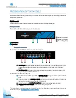
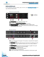
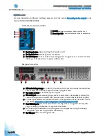
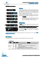
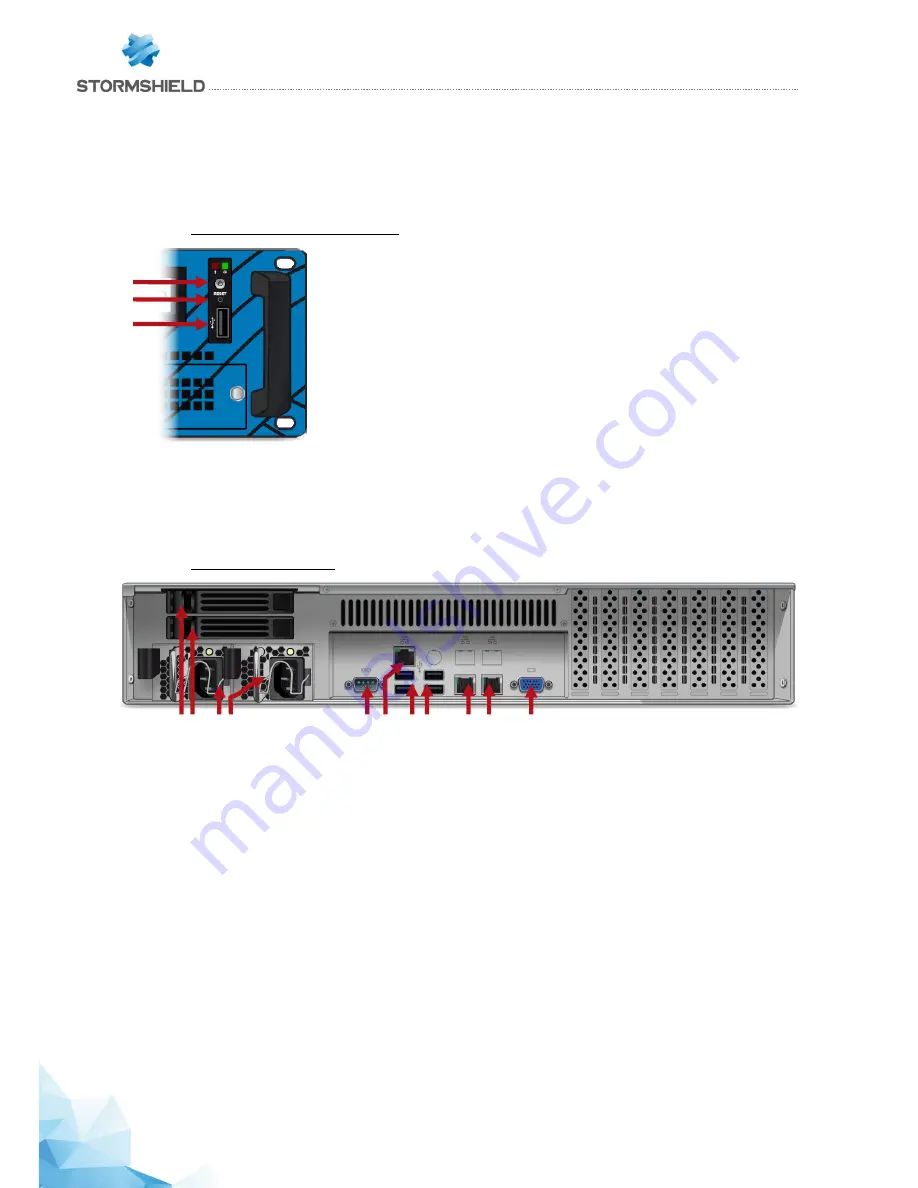
Front panel: connectors and LEDs
1
.
The Power button allows switching the Firewall on or off.
2
.
The Reset button: electrically resets the Firewall.
3
.
The USB 2.0 port can be used for secure configurations or upgrades. You can also connect a
USB key, a USB keyboard or an approved USB modem.
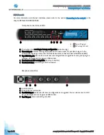
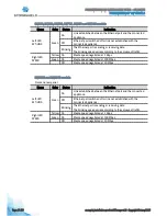
Rear panel: connectors
1
.
SSD racks for log storage (2 in RAID 1). The LEDs on SSD racks confirm whether the SSD has
been accessed (bottom blue LED) and installed (top green LED).
2
.
Two mains sockets for redundant power supplies.
3
.
The serial port allows accessing the product in console mode; it is possible to connect the
Firewall directly from a computer. The default baud rate on this model is 9600 baud (8N1).
4
.
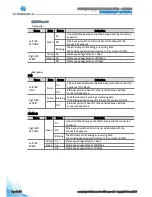
A network port dedicated to the administration of the appliance via IPMI. Please refer to the
appendix for
information on the configuration and administration via IPMI
.
5
.
Four USB 2.0 ports that can be used for secure configurations or upgrades. You may also
plug in a USB key, USB keyboard or approved USB modem.
6
.
Two network ports dedicated to the management of the appliance or a High Availability
configuration (from left to right: MGMT1 and MGMT2).
7
.
The VGA port allows connecting a monitor.
1
2
3
2
5
1
3 4
6
7
2
1
1
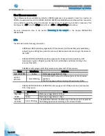
Red LED: indicates overheating or hardware failure (fans)
2
Green
Power
LED: indicates whether the Firewall is powered up.


