background image

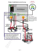
Other application ideas see fig 1-4 ( previous page)

Fig 1:

Most common installation, simply connect the 


charger between the starter battery and the secondary 
(house/bow  thruster)  bank.  The  starter  battery  stays 
between  13-14V  and  the  secondary  goes  to  14.1V-
15.1V.  This  setup  is  especially  good  when  the 
secondary battery is distant from the starter, like a bow 
thruster.

Fig  2:

This  option  shows  the  use  of  the  charger  in 


conjunction  with  a  split  charging  system.  Here  an 
additional  battery  bank  is  present,  simply  drop  the 
charger between secondary battery and this additional 

battery.  The  charger  can  also  transform  a  single 
output charger into a dual output.

Fig 3:

This option shows a situation on many boats 


or camper vehicles where there may be 3x battery 
banks.  Simply  put  2x  chargers  on,  and  they  will 
ensure both banks are catered for. It is immaterial if 
one bank is further away than another.

Fig 4:

This option focuses on charging a large house 


bank from multiple charging sources. Whether the 
charge comes from a generator, engine or old single 
stage  battery  charger  a  battery  to  battery  charger 
shall provide a much improved charging rate from 
these sources to the extensive house bank. 

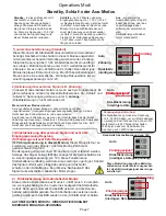
1) 

Voltage select.

Pressing this button allows you to view 3 voltages:


a) Input voltage to unit (indicated by yellow LED 2 on).
b) Output voltage from unit ( yellow LED 7 on ).
c)  Voltage  at  end  of  remote  sense  wire  (if  used)   
indicated by yellow LED 7  flashing.
2) In conjunction with the remote panel voltage button 1, 
If on, this showing the voltage reading displayed is the 
input voltage. If in conjunction with temperature button 8, 
this  shows unit  temperature. 
3)  LCD  screen  showing  digits.  Also,  red  screen  = 
WARNING. Green screen all ok. Blue = Charging. 
4)  LED  4-5-6  emulate  the  3  charge  indicators  on  the 
main box, 4 ( blue ) = constant current. 
5)  Absorption.
6) Float. 
7)  In  conjunction  with  Voltage  button  1.  If  on,  this  is 
showing that the voltage reading displayed is the output 
voltage. If flashing then the voltage displayed reading is 
the voltage at the end of the remote sense cable, if used.
In conjunction with temperature button 8, display shows 
battery temperature. 
8)  Temperature  information  selection,  by  pushing  this 
button you can select 2 temperatures: 
 

a) Unit temperature indicated by LED 2 and 

screen showing ‘C’ for degrees Celsius or ‘F’ for degrees 
Fahrenheit, depending on your setup.
 

b) Battery temperature indicated by LED 7 on  

selection and screen showing ‘C’ for degrees Celsius or 
‘F’ for degrees Fahrenheit, depending on your setup.
9) Fault, reference light on will also show a fault number 
on the screen, please reference this number against the 
fault.

E01 = High voltage input
E02 = High voltage output
E03 = High unit temperature
E04 = High battery temperature
E05 = No output voltage 

Preset voltages: (x2 for 24V models).

Minimum input voltage the unit will run at 13.0V.
Switch off and sleep mode happens below 12.8V for at 
least 15 minutes.
Power consumption on sleep mode is 5 mA (0.005A).
Maximum input voltage trip 15.5V.
Maximum output voltage trip 15.5V.
All voltages refer to a default temperature of 20 deg C.
If the battery temperature sensor is fitted these voltages 
will be less dependant on the battery temperature.

WARNING

If all LEDs flash and the fan is running, there is a fault 
and the unit needs to be disconnected and returned to 
factory.

WARNING

The  battery  temperature  sensor  adjusts  the  charger 
voltage according to the temperature on the batteries. 
The  voltage  will  be  higher  or  lower  than  the  default 
value.  In  case  of  very  low  temperatures,  the  voltage 
could exceed 15V easily. Check your equipment if it is 
capable. Or else, disconnect the temperature sensor.

Technical data:
Input voltage range:  11 - 16VDC
Output voltage range:  13 - 15.1VDC
Maximum input current:  60A / 120A / 180A  +/- 10%
Min. Input Voltage to Charge/Boost: 
 

13.3V (default)


12.2V (regenerative braking)

Unit sleep mode:  0.2V below Input Voltage 
High Input Voltage Alarm: 16.0V
High Output Voltage Alarm: 16.0V+ Temp compensation
High Unit Temperature Alarm: 100°C
High Battery Temperature Alarm: 55°C
High Voltage Drop Alarm: > 1.5V between out + battery
Low Input Voltage Warning: 11.0V
Low Output Voltage Warning: 11.0V
Minimum Output Voltage:  > 4.0V
Battery Temperature Compensation:  18mV/°C

High Battery Temperature Alarm: 55°C
High Voltage Drop Alarm: > 1.5V between out + battery
Low Input Voltage Warning: 11.0V
Low Output Voltage Warning: 11.0V
Minimum Output Voltage:  > 4.0V
Battery Temperature Compensation:  18mV/°C

Remote control panel (see next page)

   Page 10

Summary of Contents for BBW12120

Page 1: ...ng in a Euro 6 vehicle you may have to use an ignition feed to the unit When the ignition is live unit starts charging may take up to 60seconds Please read the manual for additional information If in doubt and installing on a New Euro 6 use ignition feed Main Power Terminals Input Output Sterling Power Products H Charge Float In Unit Out Rem Batt V 12 2 Temp Menu Change Volts Select Audible alarm ...

Page 2: ...try profiles between 14 0 15 5V consult battery manufacturer A rule of thumb Higher voltages result in faster charging and lower voltage result in slower charging After a period of time calculated by the software when the auxiliary batteries are full the system will float the batteries at approximately 13 5V x2 for 24V It always ensures the engine battery comes first Other features included in thi...

Page 3: ...ormance reduction algorithm in the software to preventunnecessaryoverchargingwhenbatteryishot 4 x Flash Out Batt not recognised possible reverse polarity The unit will not engage this is a safety protection circuit If the installation is new then check the battery is not reverse polarity or if the battery is below 4V the unit will not recognise it In this case it may be necessary to jump start the...

Page 4: ...pplication Fuses Fuses are there to protect cable runs through bulkheads etc A fuse should be rated to about 40 50 higher than the maximum current expected E g for a 60A product use about an 80A fuse The fuse should be within 200m of the battery 80 amp fuse on 60 amp model 140 amp fuse on 120 amp model Page 4 F A N 12V 40 mm fuse optional remote sense only for long runs fuse IN OUT Negative Positi...

Page 5: ...t the battery type With the lid removed and in your hand swipe the magnet built in against the area as marked on the drawing Simply hold the lid magnet against the box in this area if you have made correct contact with the magnetic internal switch during the 5 seconds the yellow is flashing the yellow LED will go off and the red LED will flash hold this area this shows you have hit the spot magnet...

Page 6: ...ommendation of Exide set at a voltage of 14 4V for about 10 12 hours The unit then drops to float Gel U S A spec For some reason unknown to us the American gel manufactures want a different charging profile than the European ones Don t ask us why if in doubt ask the battery supplier Gels have a max charging voltage of 14 1V Sealed lead acid A G M This is set to a maximum charge voltage of 14 4V wi...

Page 7: ...n when live feed is re established and input voltage is 13 3V there is a 10 second delay 1 Automatic activation default setting The product comes with the auto and ignition linked together This means that there are no external activation requirements for the product When the input voltage goes above 13 3V alternator or battery charger is working then the unit will simply engage and boost the outpu...

Page 8: ...tive braking Regenerative braking fix function 1 3 A new very serious issue for auxiliary charging systems has now been introduced in a lot of vehicles and small vans it is called It is a great idea as regenerative braking far as the primary vehicle is concerned as it adds extra MPG to the vehicle s specification However it is an unmitigated disaster as far as the auxiliary battery charging system...

Page 9: ...can be used to charge extra battery banks from the boat s Inboard engines outboard engines vehicle engines cars lorries vans and generator engines Simple installation if you wish to charge 2 x extra battery banks App licat ion idea s fig 1 fig 2 fig 3 fig 4 Engine starter battery Starter Mtr Domestic aux battery bank trailer bow Engine Engine starter battery alternator Starter Mtr Additional batte...

Page 10: ...re 8 Temperature information selection by pushing this button you can select 2 temperatures a Unit temperature indicated by LED 2 and screen showing C for degrees Celsius or F for degrees Fahrenheit depending on your setup b Battery temperature indicated by LED 7 on selection and screen showing C for degrees Celsius or F for degrees Fahrenheit depending on your setup 9 Fault reference light on wil...

Page 11: ...ost voltage half full toggle HI means full toggle to Low means half CL Current limit level adjust 100 100 default max 90 90 80 80 30 30 buC turn Buzzer on off default on Left button for off and right button for on Autoscroll on off default off Left button for off and right button for on Asc change contrast value from 0 to 7 default 3 Left button down and right button up con change backlight colour...

Page 12: ...rption is 3h30mins then conditioning shall only be 30mins etc Setting Float voltage 12 0V Conditioning voltage 0 1V intervals The Float LED on the remote shall turn on The default value is 12 0V if previously not set If the value is not 12 0V it has been previously changed Change this voltage value by pressing the right and left button to toggle through the values Once the appropriate voltage has ...

Page 13: ...eturns for any reason will require a proof of purchase with the purchase date The proof of purchase must be sent with the returned shipment If you have no proof of purchase call the vendor who supplied you and acquire the appropriate documentation To make a claim under warranty call our customer care line number can be found on www sterling power com and www sterling power usa com We will make the...

Page 14: ...ll entfernen Sie bitte den Magneten Dieser befindet sich unter dem Aufkleber über dem Schriftzug magnetic swipe ACHTUNG ab Firmware Version 21 Ab ca April Mai 2015 mit automatischer Senkung der Eingangsspannungsregelung für 120 Sekunden für Fahrzeuge mit Rekuperation EURO6 bluemotion etc BBW1260 60A 12V 12V BBW12120 120A 12V 12V Sterling Power Products H Charge Float In Unit Out Rem Batt V 12 2 Te...

Page 15: ... das Gerät auf maximal 15 5V hochtransformiert entsprechend der Einstellung des Batterietyps Nachdem die Batterien geladen wurden wird die Spannung auf eine Erhaltungsspannung herabgesenkt Es können zusätzlich ein Batterie Temperatur Sensor ein Batterie Spannungs Sensor und ein Ein Aus Signal angeschlossen werden Eine Fernanzeige bedienung ist optional erhältbar Vorteile 1 Einfache Installation Da...

Page 16: ...N 40 mm Aluminium Kühlkörper 8 6 7 5 1 2 3 4 13 12 15 14 17 21 16 19 18 20 12V 60A Modell Lüfteranschluss IN OUT 11 10 9 Negativ Positiv F A N 40 mm Aluminium Kühlkörper 8 6 7 5 1 13 12 14 17 21 16 19 18 20 12V 120A Modell F A N 40 mm Aluminium Kühlkörper 8 5 Lüfteranschluss 2 3 4 6 7 Seite 16 15 ...

Page 17: ...altung 2 Signal Zündung gesteuert 3 geringere Eingangsspannungs Regelung z B bei Euro6 Motoren mehr Information auf den folgenden Seiten Fuses Sicherungen Sicherungen sind dazu gedacht Kabel und Geräte vor hohen Strömen abzusichern Wählen Sie immer eine Sicherung welche 50 höher als der maximale Strom ausgelegt ist Bei einem 60A Gerät sollten Sie somit eine 80A 100A Sicherung verwenden fuse AUS GA...

Page 18: ...ung des Batterietyps verändert werden kann Wenn Sie dieses Zeitfenster verpasst haben oder die Einstellung nicht entsprechend funktioniert hat dann ist das kein Problem Entfernen Sie das positive oder negative Kabel wieder und das Gerät kann vonAnfang an gestartet werden Der Vorgang 1 4 wiederholt sich dann Einstellung Programmierung Batterietyp Während des Startvorganges nach Anschluss der Versor...

Page 19: ...nnungen nach Unten am Nächsten Z B empfiehlt der Hersteller 14 5V muss ein Batterietyp mit max 14 4V gewählt werden Blaue LED Anzahl Blinks Batterietypen Spannungen Batterie Temperatur Sensor Bei Verwendung eines Temperatursensor wird die Ladespannung entsprechend der Temperatur angepasst Die Temperaturkompensation beträgt 18mV C bei LiFePO4 erfolgt KEINE Kompensation Beim LiFePo4 Batterien und in...

Page 20: ...adegerät die Servicebatterie bis zu einer Eingangsspannung von 10V Diese Funktion kann Starterbatterien entladen wenn die Lima Leistung zu gering ist Sobald das Signal entfernt wird stoppt die Ladung und das Gerät schaltet in den Schlafmodus Es gibt keine Nachlaufzeit Das Signal muss abschalten sobald der Motor stoppt Operations Modi Zündungssignal Ein Aus Die Signalspannung muss eine Spannung von...

Page 21: ...hutz Das Gerät hat einen Verpolungsschutz D h liegt eine Spannung von weniger als 4V an wird der Ladevorgang nicht gestartet Dieser Verpolungsschutz ist beim Batterietyp LiFePo4 NICHT aktiv Achten Sie unbedingt auf die richtige Polung Lüftertausch Im Falle eines defekten Lüfters kann dieser sehr einfach getauscht werden Es handelt sich um einen 40mm Lüfter Diesen können Sie entweder im Elektronik ...

Page 22: ...rgung des Gerätes und schließen Sie es nach einigen Sekunden wieder an Blinkt es wieder dann müss das Gerät zur Reparatur eingeschickt werden Schlafmodus Aufwachen Hat das Gerät in den Schlafmodus geschaltet wird nur jede Minute überprüft ob die Spannung hoch genug ist um wieder aufzuwachen und den Ladezyklus zu starten Deshalb kann es bis zu einer Minute dauern bis das Gerät an zu Laden anfängt o...

Page 23: ...en Drucktaster für mindestens 3 Sekunden gedrückt Es erscheint entweder OFF oder ON im Display je nachdem welche Aktion möglich ist Grundsätzlich ist diese Funktion nur möglich wenn das Gerät nicht im Schlafmodus ist Wichtig Ist das Gerät mit der Fernbedienung ausgeschaltet worden geht es zwar in den Schlafmodus wenn die Eingangsspannungabfällt steigtdieSpannungwiederan Motorwirdgestartet bleibtda...

Page 24: ...ard 12 4V Mit dem linken br9 Schalter können Sie den Wert verringern mit dem rechten den Wert erhöhen Farbwechsel Spannung von grün zu blau 12 4 16 0V default 13 4V Press right b9b button to increase value press left button to decrease value Hold to accelerate Zeit der LED Anzeige 1 600 Sekunden 0 immer an standard 60 Erhöhen sie LEd den Wert durch drücken des rechten Schalters verringern durch de...

Page 25: ...tellt drücken Sie den linken Taster Select 13 Die LEDs In Unit und Condi leuchten Die mindest Ausgleichsladungszeit in Minuten wird angezeigt Möchten Sie diesen Wert ändern dann drücken Sie den rechten Taster Change Siehe auch Pkt 5 14 Haben Sie den gewünschten Wert eingestellt drücken Sie den linken Taster Select 15 Die LEDs Out Rem Batt und Condi leuchten Die maximale Ausgleichsladungszeit in Mi...

Page 26: ...seite erfahren Grundsätzlich sollte immer überprüft werden ob alle Kabel korrekt verbunden sind und ob alle Sicherungen funktionieren und nicht durchgebrannt sind Auch Korrosion kann erheblichen Einfluss auf den Stromfluss haben Ein und Ausschalten des Gerätes mit einer Pause von mindestens 10 Sekunden komplett stromlos machen kann auch zu einer Fehlerbehebung führen sollte sich die Software aufge...

Reviews: