62
9.
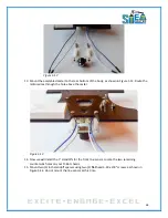
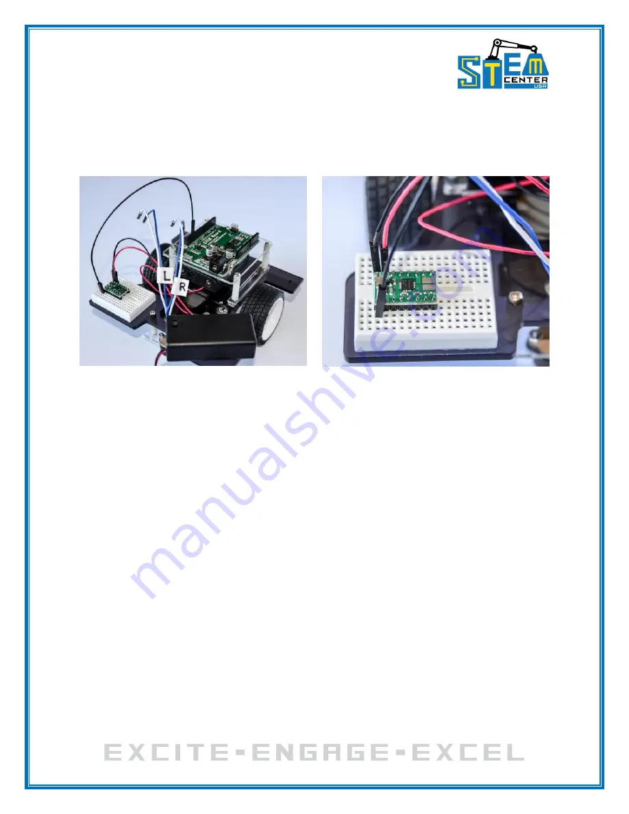
Connect the following wires, as shown in Figures 6.9 and 6.10:
a.
Ground (black) male-male wire from the STEM Board to motor controller pin 1.
b.
Battery pack negative (black) wire to motor controller pin 16.
Figure 6.9
Figure 6.10
10.
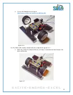
Wire the left and right motors to the motor controller, as shown in Figure 6.11.
Summary of Contents for Pi-Bot v2.00
Page 67: ...67 Figure 6 15 ...
Page 78: ...78 UltraSonicSensorTestwithLED Program ...
Page 80: ...80 ObstacleAvoidance Program ...
Page 82: ...82 ObstacleAvoidancewithLED Program ...
Page 83: ...83 ObstacleAvoidancewithLED Program CONTINUED ...
Page 90: ...90 Download and run the following program LineFollowing Program ...
Page 91: ...91 LineFollowing Program CONTINUED ...
Page 94: ...94 AdvancedLineFollowing Program CONTINUED ...
Page 95: ...95 AdvancedLineFollowing Program CONTINUED ...
Page 96: ...96 AdvancedLineFollowing Program CONTINUED ...
Page 110: ...Appendix B Complete Pi Bot Wiring Schematic ...

