52
21.
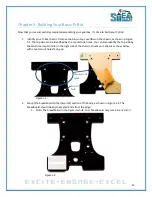
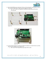
Attach the STEM Board microprocessor to the top of the clear plastic mounting plate using four
(4) 4-40 x 3/8” screws and four (4) 4-40 nuts. See Figures 5.20 and 5.21.
a.
Note: There is only one configuration that allows the STEM Board to fit onto the
mounting plate.
Figure 5.20
Figure 5.21
22.
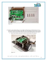
Locate the clear battery pack rails, there should be two wider ones and two thinner ones. Next,
get four (4) 4-40 x
1/2"
screws. See Figure 5.22.
a.
Note: You will have to peel off the brown layer from the rails.
Summary of Contents for Pi-Bot v2.00
Page 67: ...67 Figure 6 15 ...
Page 78: ...78 UltraSonicSensorTestwithLED Program ...
Page 80: ...80 ObstacleAvoidance Program ...
Page 82: ...82 ObstacleAvoidancewithLED Program ...
Page 83: ...83 ObstacleAvoidancewithLED Program CONTINUED ...
Page 90: ...90 Download and run the following program LineFollowing Program ...
Page 91: ...91 LineFollowing Program CONTINUED ...
Page 94: ...94 AdvancedLineFollowing Program CONTINUED ...
Page 95: ...95 AdvancedLineFollowing Program CONTINUED ...
Page 96: ...96 AdvancedLineFollowing Program CONTINUED ...
Page 110: ...Appendix B Complete Pi Bot Wiring Schematic ...

