48
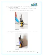
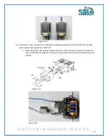
Figure 5.12
13.
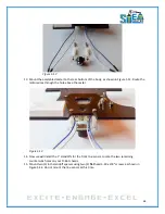
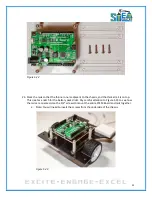
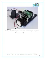
Mount the assembled caster to the rear bottom of the body, as shown in Figure 5.13. Route the
motor wires through the hole above the caster.
Figure 5.13
14.
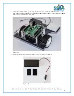
Now we will install the 1” standoffs for the front line sensor. Locate the two remaining
countersunk holes on your Pi-Bot chassis.
15.
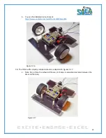
Mount two (1) inch standoff spacers using two (2)
flat
head 4-40 x 3/8” screws, as shown in
Figure 5.14. Do not mount the line sensor at this time.
Summary of Contents for Pi-Bot v2.00
Page 67: ...67 Figure 6 15 ...
Page 78: ...78 UltraSonicSensorTestwithLED Program ...
Page 80: ...80 ObstacleAvoidance Program ...
Page 82: ...82 ObstacleAvoidancewithLED Program ...
Page 83: ...83 ObstacleAvoidancewithLED Program CONTINUED ...
Page 90: ...90 Download and run the following program LineFollowing Program ...
Page 91: ...91 LineFollowing Program CONTINUED ...
Page 94: ...94 AdvancedLineFollowing Program CONTINUED ...
Page 95: ...95 AdvancedLineFollowing Program CONTINUED ...
Page 96: ...96 AdvancedLineFollowing Program CONTINUED ...
Page 110: ...Appendix B Complete Pi Bot Wiring Schematic ...

