


59
a.
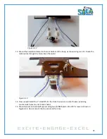
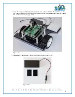
Note: The motor controller has multiple solder pads on the right side of the board.
These solder pads will be used to orient the controller on the breadboard. When
installing the controller in the breadboard, make sure the solder pads are on the right
side of the body as shown in Figure 6.4.
Figure 6.3
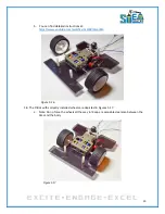
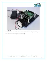
4.
Place the motor controller in the breadboard, as shown in Figure 6.4.
Figure 6.4
Summary of Contents for Pi-Bot v2.00
Page 67: ...67 Figure 6 15 ...
Page 78: ...78 UltraSonicSensorTestwithLED Program ...
Page 80: ...80 ObstacleAvoidance Program ...
Page 82: ...82 ObstacleAvoidancewithLED Program ...
Page 83: ...83 ObstacleAvoidancewithLED Program CONTINUED ...
Page 90: ...90 Download and run the following program LineFollowing Program ...
Page 91: ...91 LineFollowing Program CONTINUED ...
Page 94: ...94 AdvancedLineFollowing Program CONTINUED ...
Page 95: ...95 AdvancedLineFollowing Program CONTINUED ...
Page 96: ...96 AdvancedLineFollowing Program CONTINUED ...
Page 110: ...Appendix B Complete Pi Bot Wiring Schematic ...


