13 / 16
13 / 16
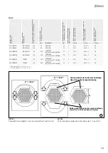
24
25
45°
16BL-CP/...
16BL-CS/...
16BL-CP/...
16BL-CS/...
45°
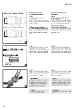
Procedura podłączania
Plugging procedure
(ill. 24)
Sworzeń blokujący na złączu żeńskim musi znajdować się
w pozycji „otwartej” (rys� 26, strona 14)�
Oznaczenia na wtyku i gnieździe muszą być w linii� Włożyć wtyk
do gniazda do oporu i obrócić gniazdo o 45° w prawo, aż zasko-
czy blokada bagnetowa�
W razie potrzeby przestawić sworzeń blokujący w położenie „za-
mknięte” (rys� 26, strona 14)�
(ill. 24)
The locking pin on the female connector must be in the “open”
position (ill� 26, page 14)�
The markings on the plug and socket have to be lined up� Mate
the plug with the socket up to the stop and turn the socket 45° to
the right until the bayonet lock engages�
If desired, turn the locking pin to the “closed” position (ill� 26, page
14)�
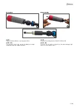
Procedura testowa
Test procedure
Przekręcając złącza sprawdzić, czy mechanizm blokujący jest
załączony�
Podjąć próbę rozłączenia i sprawdzić czy będzie ono możliwe�
By twisting the connectors test that the locking mechanism is
engaged�
By attempting to simply pull the connectors apart, test that the
connection in this position can no longer be mechanically sepa-
rated�
Informacja:
Prawidłowe ryglowanie następuje dopiero po włożeniu tulei�
Note:
Correct interlocking is achieved only after engagement of the
sleeve�
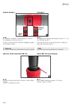
Procedura odłączania
Unplugging procedure
(ill. 25)
Sworzeń blokujący na złączu żeńskim musi znajdować się
w pozycji „otwartej” (patrz rys� 26, strona 14)�
Aby zwolnić, odciągnąć tuleję złącza żeńskiego i obrócić gniazdo
o 45° w lewo, aż się zatrzyma (wyrównanie oznaczeń)� Rozdzielić
złącza męskie i żeńskie�
(ill. 25)
The locking pin on the female connector must be in the “open”
position (see ill� 26, page 14)�
To release, pull back the sleeve of the female connector and turn
the socket 45° to the left, until it stops (coincidence of the mark-
ings)� Separate male and female connectors�
Oznakowanie / Marking
Wyrównane logo
Logo lined up


