3 / 16
3 / 16
TECHNICAL CONSIDERATIONS according to UL File E470532
Use
:
For use only in (or with) complete equipment where the acceptability of the combination is determined by UL LLC�
Conditions of Acceptability:
These devices are not suitable for interrupting the flow of current by connecting or disconnecting the mating connector�
These devices have been investigated with the applicable requirements in the Standards UL 486A-486B only with reference to the
crimp contacts: they have been investigated and found in compliance with the applicable requirements of the mentioned standards�
The acceptability of the housing, gasket, cable gland, mounting means and any accessories should be investigated in the end use
application�
These devices have been investigated and tested when the crimp contacts are assembled on their intended cable size using the Crimp
Tool and Die indicated in the the manufacturer’s installation instructions�
The crimp contacts of these devices are suitable for factory and field wiring�
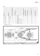
The power inlet 16BL-PP is for mounting on panel and is provided with stud and nut terminal and optional protective cover DE 16N,
optional angled adapter WA-ID/S21 and optional accessory switch MSW-16BL-PP indicating the locking status, rated 5 A, 125/250
VAC, 1 A, 48 VDC, for use with prepared conductors, as example ring cable lugs�
The power inlet 16BL-MP is for mounting directly onto bus bar using the stud and nut terminal� The acceptability of these connections
should be judged in the end use�
The suitability of the insulating materials for use at 1000 V rating has not been verified except for sign or luminaire as permitted by the
Standards UL 486A-486B�
The Dielectric test (puncture) was conducted at 3400 V ac based on a maximum voltage rating of 600 V� Any additional evaluation and
testing for use at more than 600 V should be considered in the end use�
These devices (full assembly) have been subjected to a Temperature test with the rated currents�
The devices shall be used with Copper Concentric Class B or Copper Compressed Class B or Copper Concentric Class 5 conductors
insulated for a minimum of 90°C�
The insulating material used in these devices to make the “housing” of the live parts complies with the direct support requirements of
UL 746C, the Standard for Polymeric Materials - Use in Electrical Equipment
Instrukcja bezpieczeństwa
Safety instructions
Przed każdym użyciem złącza, należy je wcześniej sprawdzić
pod kątem wad zewnętrznych (szczególnie izolacji)� W razie wąt-
pliwości dotyczących bezpieczeństwa należy skonsultować się
ze specjalistą lub wymienić złącze�
Each time the connector is used, it should previously be inspect-
ed for external defects (particularly the insulation)� If there are any
doubts as to its safety, a specialist must be consulted or the con-
nector must be replaced�
Złącza wtykowe są wodoszczelne zgodnie ze stopniem ochrony
produktu IP�
The plug connectors are watertight in accordance with the pro-
duct specific IP protection class�
Niepodłączone złącza należy chronić przed wilgocią i brudem�
Zabrudzone części męskie i żeńskie nie mogą być łączone ze
sobą�
Unmated plug connectors must be protected from moisture and
dirt� The male and female parts must not be plugged together
when soiled�
Specyfikacje techniczne złącza różnią się w zależności od kla-
syfikacji systemu, IEC lub UL (napięcie znamionowe i prąd)� Aby
uzyskać więcej informacji, patrz katalog produktów�
The technical specifications of the connector vary depending on
the system classification, IEC or UL (rated voltage and current)�
For more information, please see the product catalog�
Przydatna porada lub wskazówka
Useful hint or tip
Więcej danych technicznych znajduje się w katalogu produktu�
For further technical data please see the product catalog�


