background image

FirstLine UPS


Form No. 003-2323 Rev B 


26 

 
Manual Transfer to Bypass 

 
Verify  that  the  bypass  input  is  qualified  by  observing  that  the  bypass  indicator  is  green. 
While holding down the ESC key, press the up-arrow key. When the conditions are met for 
a transfer to bypass (bypass input is qualified and inverter is synchronized to bypass), the 
static  switch  will  transfer  the  load  to  bypass.  After  a  few  seconds,  the  mimic  display  will 
update to show this. 
 

Manual Transfer to Inverter 

 
This procedure enables an automatic transfer to inverter. While holding down the ESC key, 
press the down-arrow key. When the conditions are met for a transfer to inverter (inverter is 
running  and  synchronized  to  bypass),  the  static  switch  will  transfer  the  load  to  inverter. 
After a few seconds, the mimic display will update to show this. 
 

External Bypass Arrangement 

 
If the UPS is connected to a Staco Maintenance Bypass Switch, refer to the manual for that 
product  for  proper  operation.  The  MBS  is  equipped  with  a  label  that  describes  common 
transfer  operations  and  a  brief  summary  is  provided  below.  Bypass  switches  provided  by 
others are not recommended as they are not equipped with the proper interlocks to prevent 
backfeed,  a  hazardous  condition  that  can  be  lethal  to  service  personnel.  Use  of  a  non-
Staco bypass switch may void the UPS product warranty. 
 
The normal mode of operation (i.e. not bypass) requires that switches 1 and 3  in the MBS 
are closed. The UPS should be operating in this state. To transfer operation of the load to 
Maintenance  Bypass  mode,  first  perform  a  manual  transfer  to  bypass  per  the  procedure 
above. Verify that the mimic display changes to show that the load is now connected to the 
bypass line. Close Switch 2 in the MBS, then open Switch 3. Turn off the UPS, if desired,, 
then open Switch 1. 
 
To  return  from  Maintenance  Bypass  to  Normal  mode,  close  Switch  1  and  start  the  UPS, 
Select manual Transfer to Bypass mode. Verify that the UPS is running and that the mimic 
diagram shows that the output is being supplied from the bypass line. Close Switch 3, then 
open Switch 2. Select Automatic Transfer to Inverter per the procedure below. 
 
If the UPS fails to start and it is desired to get power to the load, open Switches 1 and 3 on 
the  MBS,  then  close  Switch  2.  The  load  is  now  powered  from  the  bypass,  Note  that  the 
UPS logic is not involved in the decision to apply bypass power to the load, so there is no 
assurance  that  the  bypass  source  is  suitable  for  powering  the  load.  This  procedure  is 
performed at the user’s risk. Also note that the UPS will not start when the bypass source is 
out of specification. 
 

Summary of Contents for FirstLine

Page 1: ...STLINE UPS 25KVA 30KVA AND 37 5KVA Form No 003 2323 Rev B 09 04 2009 301 Gaddis Boulevard Dayton Ohio 45403 U S Toll Free 866 261 1191 937 253 1191 Fax 937 253 1723 Web site www stacoenergy com User s...

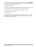
Page 2: ...00 meters the output load capability must be derated by 1 for each 100 meters above 1000 meters Verify that the installation includes an input breaker of the proper rating Verify that the wiring is co...

Page 3: ...nternal Battery 18 Section 5 20 Communication 20 Customer Interface 20 Section 6 22 Operation 22 Display Functions 24 Section 7 25 Initial Start Up 25 Normal Operation 25 Manual Transfer to Bypass 26...

Page 4: ...37 5kVA 1 Figure 2 UPS on pallet 7 Figure 3 Shipping Bracket 8 Figure 4 Lifting fork area 9 Figure 5 Leveling foot being adjusted down to the floor 10 Figure 6 Bottom View 12 Figure 7 Terminal Blocks...

Page 5: ...ctrical systems the UPS supplies clean consistent power that sensitive electronic equipment requires for reliable operation During brownouts blackouts and other power interruptions batteries provide e...

Page 6: ...80 208Y 120 8 Tall FLU 30T 42 1 I 480 480Y 277 8 Tall FLU 30T 44 1 I 208Y 120 208Y 120 22 Tall FLU 30T 20 2 208Y 120 208Y 120 8 Tall FLU 30T 20 1 I 220Y 127 220Y 127 11 Short FLU 30S 22 1 220Y 127 220...

Page 7: ...hold option devices to be used in conjunction with the FirstLine UPS The enclosure is styled to match the UPS and includes provisions for terminating a number of conduits to facilitate wiring Availabl...

Page 8: ...ic heaters d Use caution when servicing batteries Battery acid can cause burns to skin and eyes If acid is spilled on skin or in eyes flush acid with fresh water and contact a physician immediately e...

Page 9: ...near water or excessive humidity 95 maximum Input and output over current protection and disconnect switches must be provided by others Batteries can present a risk of electrical shock or burn from hi...

Page 10: ...of the equipment 2 Send a copy of the damage claim within 15 days to your service representative Floor Loading When planning the installation consider the UPS weight for floor loading The strength of...

Page 11: ...rom the ship pallet 1 Remove all banding wrapping and foam protectors 2 Loosen the six 1 2 nuts and washers securing the shipping brackets to the pallet see Figures 2 and 3 3 Remove and discard the fo...

Page 12: ...so that they will not touch the floor when the cabinet is placed on the floor 6 Lift the cabinet with a forklift from the rear of the unit one to two inches 1 2 2 5 5cm above the pallet see figure 5...

Page 13: ...UPS Form No 003 2323 Rev B 9 Place forks in this area so as not to damage the leveling feet or casters Set forks to a maximum 13 inches at outside width Leveling foot 13 00 330mm Max Figure 4 Lifting...

Page 14: ...el to access the front leveling feet by pulling the panel outward at the bottom of the unit until it unsnaps and then lift up and off the cabinet see figure 9 Adjust the leveling feet as shown in figu...

Page 15: ...vailable in the short or tall cabinet 480V 60 Hz input is available when using the tall cabinet with an input transformer isolation or auto 480 480 Vac is available when using the tall cabinet with an...

Page 16: ...see figure 6 Remove plate and drill or punch hole to fit conduit bushing with Greenlee punch or similar device Make certain that the bushing will be clear in the opening in the base Mount bushing to p...

Page 17: ...sformer 3 Connect the output wires to the proper terminals shown in Figure 7 4 Replace the rear panel NOTICE FOR SUPPLY CONNECTIONS USE WIRES SUITABLE FOR AT LEAST 75 C A B C N OUTPUT INPUT N C B A Fi...

Page 18: ...208 V Isolation 120 150 37 kVA 220 V None 120 150 37 kVA 480 V Standard auto 60 75 37 kVA 480 V Isolation 60 75 UPS Rating Output Voltage Rated Max Output Current A note 2 Maximum Allowable Circuit P...

Page 19: ...PA 70 30 KVA 208V CAUTION to reduce the risk of fire connect only to a circuit provided with 125 amperes maximum branch circuit protection in accordance with the National Electrical Code ANSI NFPA 70...

Page 20: ...d load current is not needed and the appropriate circuit protection is applied UPS Rating Voltage Output Transformer Type Phase Conductor Neutral Conductor Neutral Conductor with non linear loads Grou...

Page 21: ...eeded to accommodate the extra wire or size and use that conduit size in place of the conduit size listed Conduit sizes can be chosen from NEC Table C1 type letters RHH RHW RHW 2 TW THW THHW THW 2 INP...

Page 22: ...TCH SHOULDER SCREW KEYHOLE SLOT Figure 9 Removing the UPS Front Panel Connect The Internal Battery To be performed by authorized service personnel 1 Remove front cover panel and interior panel 2 Remov...

Page 23: ...manual for the FirstLine Extended Run Time Battery Cabinet Also refer to the special notes in Section 8 of this manual 7 Reference figure 10 Connect the battery plug to the DC input plug 8 If the UPS...

Page 24: ...ed communications accessories Note TB1 TB2 TB3 TB4 plug in terminal blocks fuse and fuse cap are shipped in the zip lock bag with this manual Install them before powering up the UPS Customer Interface...

Page 25: ...terface is available The UPS shipped with an installation CD containing monitor software and an RS 232 cable The monitor software will allow a single user to connect the UPS to a computer via the RS 2...

Page 26: ...own Control Panel Functions The UPS has LCD with backlight It provides useful information about the UPS itself load status events measurements and setting see figure 14 ESC EPO Bypass Indicator Input...

Page 27: ...DC Bus Fault call for Service Battery Off System OFF Battery Green Battery is being charged or is at full charge Battery Yellow Battery is discharging Battery Red Battery fault or no battery present I...

Page 28: ...ucture Press the button to enter a submenu Press the button to select an option Press the button to cancel or return to the previous menu The following table shows the basic menu structure Table 10 Me...

Page 29: ...tion 7 Apply power to the UPS 8 Press the on off button to start the UPS Normal Operation To start the UPS press the on off power button If the bypass input is qualified voltage frequency and phase se...

Page 30: ...d a hazardous condition that can be lethal to service personnel Use of a non Staco bypass switch may void the UPS product warranty The normal mode of operation i e not bypass requires that switches 1...

Page 31: ...d c battery reaches end of discharge voltage threshold 3 Loss of output voltage is detected Automatic Transfer To Inverter The static switch will automatically transfer the load to inverter if all of...

Page 32: ...may operate during overload conditions Rectifier The rectifier is microprocessor controlled using algorithms that limit the input current to levels that protect the rectifier components If the inverte...

Page 33: ...awn from the cabinet To service the battery trays they must be removed from the cabinet by a fork lift The 3 bus bars at the back of the tray as shown in figure 15 must be removed before servicing or...

Page 34: ...econnect the cables using the markings as a guide If this is a new battery installation connect the battery cables using the procedure in the following paragraphs For a two tray single string battery...

Page 35: ...d Figure 17 Battery Installation EXTENDED RUN TIME BATTERY TERMINAL TIGHTENING TORQUE 2 3 AWG 50 inch pounds 4 6 AWG 45 inch pounds Note Size wire per local codes 6 AWG 75 C copper wire minimum to 2 A...

Page 36: ...he positive connection and the right hand terminal for the negative connection Before connecting the wires between the UPS and the Extended Battery Cabinet the UPS must be powered down the front outer...

Page 37: ...orrect Repeat this measurement for the third Extended Battery Cabinet if present The battery plugs for all strings in the Extended Battery Cabinet s can be connected at this time Stopping the Rectifie...

Page 38: ...tic switch has transferred the load to inverter UPS Maintenance The FirstLine UPS is designed to be virtually user maintenance free requiring only the occasional wipe with a damp cloth or non abrasive...

Page 39: ...removing the front cover of the cabinet If not equipped with this breaker it is necessary to remove the inner panel and unplug the red and black connectors 4 Remove the outer panel from the UPS by pu...

Page 40: ...is the optional breaker simply close the breaker to connect the battery 14 Replace the outer panels on the UPS and the battery cabinet if present 15 Reapply utility ac power to the UPS 16 Start the UP...

Page 41: ...the FirstLine extended run time battery cabinet which can be outfitted with one two or three strings of batteries and with or without a circuit breaker Connections in the UPS for the extended run time...

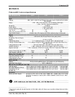
Page 42: ...r Overload 100 continuous 125 for 2 minutes 150 for 1 second Bypass Overload 110 continuous 125 for 2 minutes 150 for 10 seconds 700 for 5 cycles Output Current Amp s at 208V 70 55 83 66 104 83 Heat R...

Page 43: ......

Reviews: