FirstLine UPS
Form No. 003-2323 Rev B
Table 1-Part Numbering System .......................................................................................... 2
Table 2-Symbols .................................................................................................................. 4
Table 3-Model Floor Loadings .............................................................................................. 6
Table 4-Input/Output Terminal ........................................................................................... 13
Table 5-Ground Lugs ......................................................................................................... 13
Table 6-FirstLine UPS 10-20kVA Current Requirements ................................................... 14
Table 7-Terminal Block Wiring ........................................................................................... 16
Table 8-Torque Values for TB1, 2, 3, 4 .............................................................................. 21
Table 9-Indicator Status and Description ........................................................................... 23
Table 10-Menu Map for Display Functions ......................................................................... 24
Figure 1-The FirstLine UPS 25-37.5kVA .............................................................................. 1
Figure 2-UPS on pallet ......................................................................................................... 7
Figure 3-Shipping Bracket .................................................................................................... 8
Figure 4-Lifting fork area ...................................................................................................... 9
Figure 5-Leveling foot being adjusted down to the floor ..................................................... 10
Figure 6-Bottom View ......................................................................................................... 12
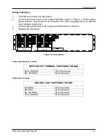
Figure 7-Terminal Blocks ................................................................................................... 13
Figure 8-UPS Wiring-Single Line Diagram ......................................................................... 17
Figure 9-Removing the UPS Front Panel ........................................................................... 18
Figure 10-Internal Battery ................................................................................................... 19
Figure 11-Communication Options and Control Terminals ................................................. 20
Figure 12-TB3 .................................................................................................................... 21
Figure 13-TB4 .................................................................................................................... 21
Figure 14-FirstLine Front Panel Display and Control Module ............................................. 22
Figure 15-Battery Tray ....................................................................................................... 29
Figure 16-Battery Tray ....................................................................................................... 30
Figure 17-Battery Installation ............................................................................................. 31
Figure 18-The FirstLine Extended Run Time Battery Cabinet ............................................ 37
Summary of Contents for FirstLine
Page 43: ......


