


FirstLine UPS
Form No. 003-2323 Rev B
21
There are five sets of form-C dry contact available as outputs. They are capable of
switching up to 30 volts (AC or DC) at up to 1 amp. Listed in order of NO, COM, NC.
TB3 terminals 1, 2, 3
– running on inverter.
TB3 terminals 4, 5, 6- battery discharging.
TB3 terminals 7, 8, 9- low battery reserve.
TB3 terminals 10, 11, 12- on bypass.
TB3 terminals 13, 14, 15- alarm present.
Figure 12-TB3
There are five sets of optically isolated open collector outputs available. They are capable
of switching up to 30 volts DC and up to 3 milliamps. Listed in order of Emitter, Collector.
TB4 terminals 1,2
– running on inverter
TB4 terminals 3,4
– battery discharging
TB4 terminals 5,6
– low battery reserve
TB4 terminals 7,8
– on bypass
TB4 terminals 9, 10
– alarm present
Figure 13-TB4
An RS-232 DCE three wire interface is available. The UPS shipped with an installation CD
containing monitor software and an RS-232 cable. The monitor software will allow a single
user to connect the UPS to a computer via the RS-232 port for local monitoring of UPS
operation.
For advanced monitoring Ethernet and SNMP are supported via the RS-232 interface with
an external adaptor. A 120 volt AC outlet has been provided on the back panel of the UPS
for powering the external adaptor. Consult the factory for more details.
The local RS-232 monitor function cannot be used at the same time as the external
monitoring adaptor.
If the UPS is connected to the Staco Maintenance Bypass Switch, there are required
connections between TB1-3, TB1-4, TB3-10, TB3-11 and the MBS. If an MBS is present,
TB3-
10, 11, 12 (“On Bypass”) contacts are not available to the user.
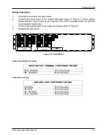
Table 8-Torque Values for TB1, 2, 3, 4
TORQUE VALUES FOR TERMINAL BLOCKS
ON CUSTOMER INTERFACE BOARD
#22 - #12 AWG
4.4 inch-pounds
1
3
TB3
Example
2
2
1
Vcc = 5.0 VDC
RL
Vo
TB4
Typical
application
Summary of Contents for FirstLine
Page 43: ......