


5
!
Please read and understand these
instructions completely before
installation to avoid possible injury, or
damage to the accessory or vehicle.
WARRANTY INFORMATION:
All SSV Works enclosures are covered by a limited lifetime warranty against defects
in material or workmanship. All SSV Works Electronics are covered by a limited 1 year
warranty against defects in material or workmanship. All Kicker Speakers are covered
by a limited 1 year warranty against defects in material or workmanship. All Kicker
Amplifiers are covered by a limited 2 year warranty against defects in material or
workmanship. Labor for replacement of defective components is not covered. Contact
SSV Works for further warranty information.
INSTALLATION NOTES
It is recommended to wrap the bag that the clamps come in around the cage before you slide the clamp onto the cage to prevent scratching.
TOOLS NEEDED FOR INSTALLATION
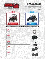
PARTS LIST IMAGES
1. US-C65 Enclosures (1 pair)
5. M6 Hex Head Bolts &
Washers x4
6. M6 Allen Socket Head Bolts
& Washers x4
3. Ring Clamp x 4
7. M6 Set Screws x 4
2. Dual Mounting Ring
Adapter x 2
- 5mm Allen Key
- 8mm Open End Wrench
Placement of the pod depends on what type of roll
cage you have (factory or aftermarket) and your
preference of where you want the pods to be installed.
In these instructions, we have installed them on the
outside vertical bars at the back of the roll cage.
4. Rear B-H2195 Speaker
Harness
SSV WORKS, 201 N. Rice Ave Unit A, Oxnard, CA 93030
www.SSVworks.com | Phone: 818-991-1778 | Fax: 866-293-6751
Cage Mount
Kicker 6.5” Speaker Enclosures
PARTS LIST 4/4