DIGIVEX Little Drive Servoamplifier
12
PVD 3530 GB 01/2005
1.3.3.3 Forcing logic inputs
The software allows the logic input to be forced to a value. Consequently, via the software, the
SPEED RANGE, CW, CCW, TORQUE inputs are able to:
"disconnect" them from the physical input.
force them by software to 0 or 1.
1.3.3.4 Stimuli / oscilloscope functions
Certain functions integrated in the drive allow the speed set point to be excited: dc voltage,
square (response at one scale), sine.
These stimuli are activated by a PC. Their result, stored in the amplifier, can be seen on the PC
screen by using the oscilloscope function (a maximum of 4 variables can be displayed
simultaneously via the PME DIGIVEX software).
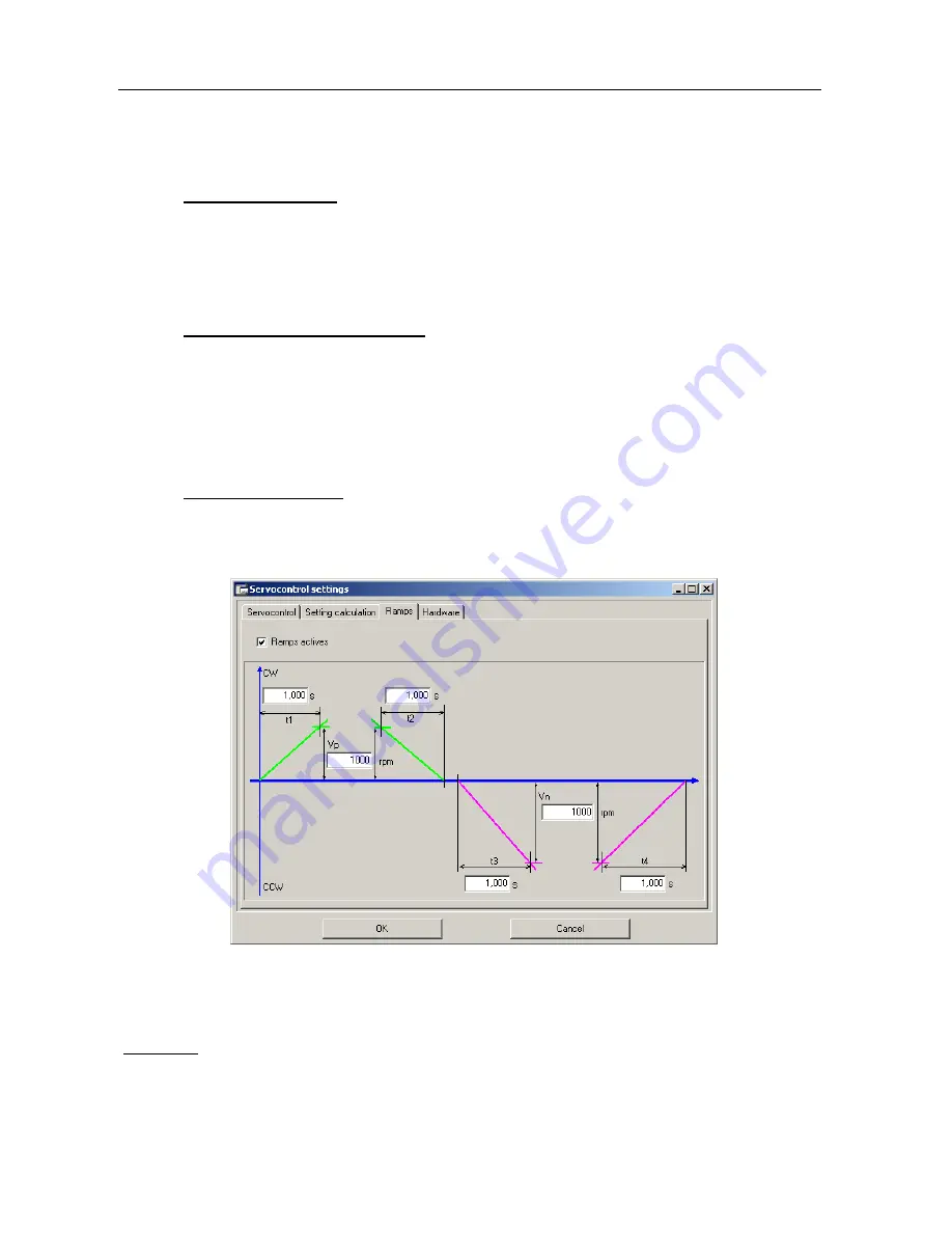
1.3.3.5 Speed ramp function
A ramp function is integrated into the drive unit for versions of software above AP516V07, running
with PME version 4.04 or above. This function is used to create time dependent linear speed
ramps. Parameters can be set in “Servo-control settings” under the “ramp” tab:
- Times t1, t2, t3, and t4 can be programmed from 0 to 1000s.
- Speeds Vp and Vn can be programmed from 0 to 50,000 rpm.
Comment:
Vp and Vn are points on the ramp; they can be defined outside of maximum motor speed.
However, servo-controls will limit the motor speed to the maximum authorized speed.
This manual was downloaded on www.sdsdrives.com
+44 (0)117 938 1800 - [email protected]


