3.696.5275.210
20
Main Power Supply
1 KW supply, 400 Vac, 50 Hz three phases (verify the electrical drawings).
Output contacts:
Dry contacts NO/NC 220 Vac, 5 Ampere.
Input contacts:
Dry contacts NO/NC not powered, 5 Ampere.
Ambient temperature:
0°C + 50°C (inside the control cabinet)*
Humidity:
5% to 95% relative non condensing.
∆
Attention: the user is responsible for electrical connections to the package.
∆
Attention: do not route signal and control wiring with power wiring in the
same conduit. This can cause interference with operation. Failure to observe this
precaution could result in damage to, or destruction of, the equipment.
∆
Attention: a power disconnect device must be installed by the user, between
the general power line and the cabinet. If the power disconnecting device is a circuit
breaker, the circuit breaker must be able to trip 25 Amperes. It is important to verify
that the main power will meet input power requirements of the control cabinet. Be
sure that input power corresponds to the nameplate voltage and frequency.
∆
Attention: unused wires in conduit must be grounded at both ends to avoid
a possible shock hazard caused by induced voltages.
* Note: if the environmental conditions bring the temperature inside the cabinet to
overcome 50°C conditioning devices are available.
Please contact your nearest Spirax-Sarco branch or agency.
Grounding the cabinet
∆
Attention: the user is responsible for conforming with all the applicable local,
national and international codes. Failure to observe this precaution could result in
damage to, or destruction of the equipment.
Use the following steps to ground
Step 1: open the cabinet door.
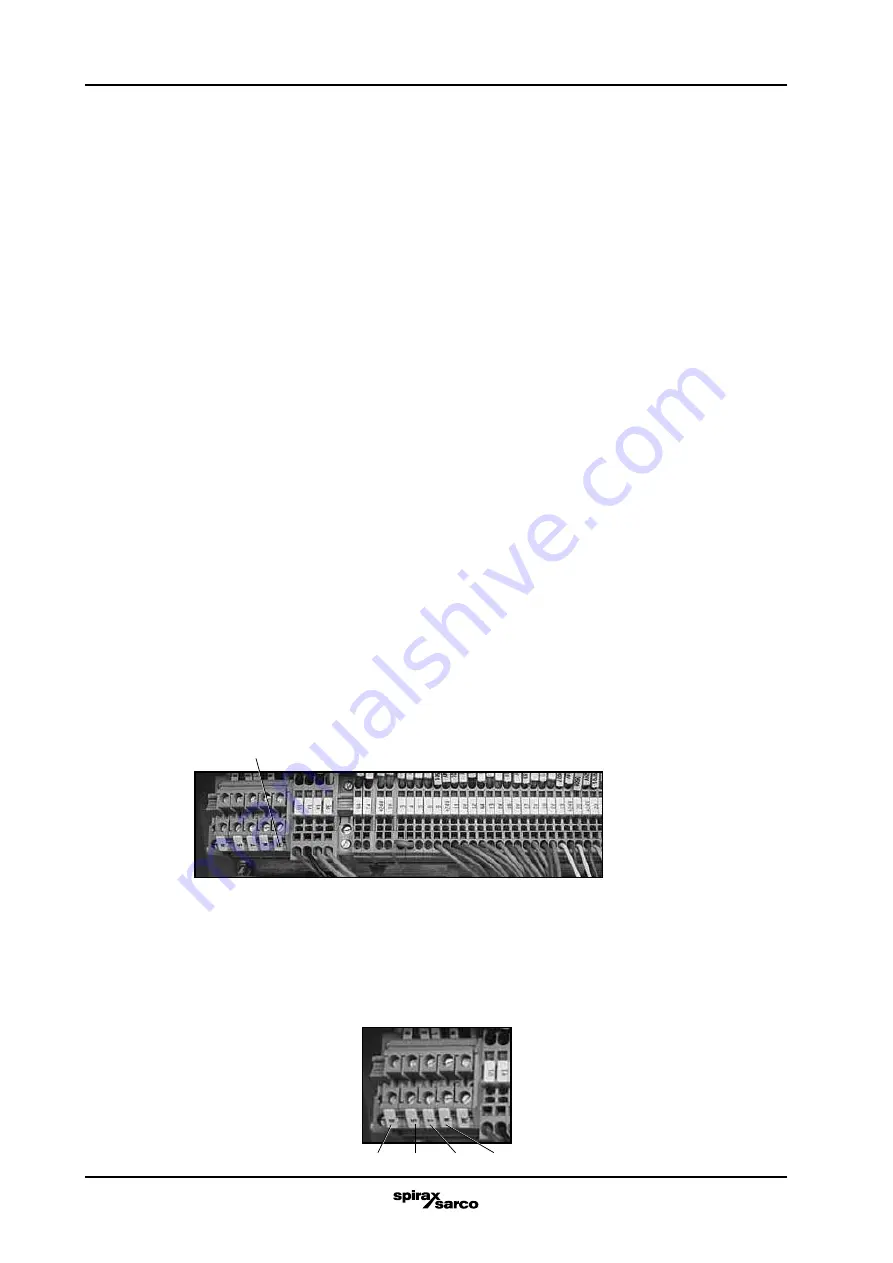
Step 2: run a ground unbroken conductor from the control cabinet ground terminal PE to
the earth ground (Fig. 11). Ground cable must be not less than 4 mmq.
Installing power inputs lines
Use following steps to connect AC input power to the control cabinet.
Step 1: wire the Ac input power leads by routing them in the cabinet unit through the plug.
Step 2: connect the 3 phase AC input + Neutral power leads to terminals R, S, T, N input
on
Terminal board (Fig. 12).
Step 3: tighten the AC input terminals.
Fig. 12
Power supply
380 VAC 50 Hz
Fig. 11
R
S
T
N
Summary of Contents for CSM-C
Page 6: ...3 696 5275 210 2...


