DF/FF MANUAL 118002-001 R
ev B
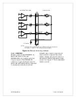
OPEN FILAMENT
(Note: LEAKAGE LIMIT /TEMP LED will signal
overtemp fault if light is steady, and leakage current
limit if the LED is blinking)
A precision DC 10V reference is
generated on the board for programming
kV, mA and other references.
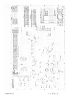
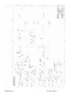
Control of the generator utilizes
sophisticated analog and digital circuitry
resulting in fast and accurate control,
protection and signaling to the user.
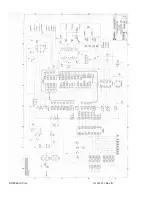
This generator is based on advanced
PWM digitally improved control and for
that purpose Unitrode UC3825 integrated
circuit is used in combination with Xilinx
FPGA XCS30. Analog signals are
digitized in A/D converter and processed
within FPGA circuits to provide
maximum accuracy and reliability.
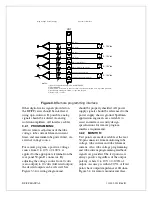
All feedback signals are sent to the user interface
through digital and D/A circuits where switching
is possible between feedback and program signals.
This allows the user to preset the desired output
before energizing high voltage.
All program voltages are typically ramped
up to set level by the digital slow start.
FPGA and accompanying A-D and D-A
converters and drivers provide system
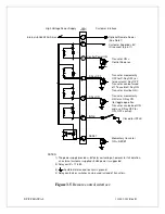
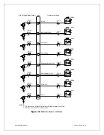
Fault Control and Indication. User
interface is processed on this PWB as
well, providing isolated relay coils,
optocouplers and open collectors contact.
4.6
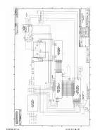
FILAMENT POWER PWB
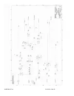
The filament inverter provides the
filament power for the X-ray tube. The
filament inverter is a high frequency,
series resonant inverter. The inverter
provides regulated current to the primary
of the filament isolation transformer. The
filament isolation transformer secondary
is connected to the output connector. For
the DC filament option, the transformer
secondary is connected to a full wave
rectifier and then to the output connector.
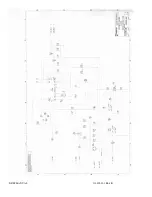
The filament PWB also provides variety
of control, diagnostic and protection
functions for AC input. One of them is
inrush current limiting during initial
charge of the DC rail filter capacitor. For
that purpose high power limiting resistors
and bypass relays are provided. Relays are
controlled by sensing and driver circuitry
on the same board.
If any abnormal condition appears
monitoring circuitry will shut down the
unit.
Neon indicator provides visual indication
when DC voltage is present across the
rails. This indicator should not be relied
upon for confirming the presence or
absence of the DC voltage. Integrated
circuits provide logic control for AC
faults conditions.
4.7
OPTIONS
Due to many variations of models and
options provided in the series, details of
actual circuits used may differ slightly
from above descriptions. Consult
Spellman’s Engineering Department for
questions regarding the principles of
operation for the series.
Summary of Contents for X3645
Page 1: ...DF FF MANUAL 1 118002 001 Rev B ...
Page 2: ...DF FF MANUAL 2 118002 001 Rev B ...
Page 28: ...DF FF MANUAL 118002 001 Rev B ...
Page 29: ...DF FF MANUAL 118002 001 Rev B ...
Page 30: ...DF FF MANUAL 118002 001 Rev B ...
Page 31: ...DF FF MANUAL 118002 001 Rev B ...
Page 32: ...DF FF MANUAL 118002 001 Rev B ...
Page 33: ...DF FF MANUAL 118002 001 Rev B ...
Page 34: ...DF FF MANUAL 118002 001 Rev B ...
Page 35: ...DF FF MANUAL 118002 001 Rev B ...
Page 36: ...DF FF MANUAL 118002 001 Rev B ...
Page 37: ...DF FF MANUAL 118002 001 Rev B ...
Page 38: ...DF FF MANUAL 118002 001 Rev B ...
Page 39: ...DF FF MANUAL 118002 001 Rev B ...
Page 40: ...DF FF MANUAL 118002 001 Rev B ...

