DF/FF MANUAL 118002-001 R
ev B
3
OPERATING INSTRUCTIONS
3.1
OPERATION
WARNING
THIS EQUIPMENT GENERATES
DANGEROUS VOLTAGES THAT MAY
BE FATAL. PROPER GROUNDING OF
ALL HIGH VOLTAGE EQUIPMENT IS
ESSENTIAL.
IMPORTANT:
Before connecting the power supply to
the AC line, follow this step-by-step
procedure.
Do not connect the power supply to
the AC line until Step H is reached.
Failure to follow these procedures may
void the warranty.
A)
Insure that the CONTROL
POWER ON switch on your remote
interface fixture is in the OFF (out)
position.
B)
Check the input voltage rating on
the nameplate of the supply and make
certain that this is the rating of the power
source to be connected. Units operate on
220VAC single phase, unless ordered
with a different input voltage.
C)
Proper Grounding Technique: The
chassis of the high voltage power supply
must be grounded to the local earth
ground and also to the tube housing
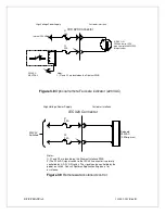
ground. See Figure 3.2 for typical
operating setup.
A three-wire cable is provided for
connecting to the AC supply. The Green
wire is for chassis safety ground
connection.
D)
Connect the X-ray cable to the X-
ray tube housing.
E)
Connect the X-ray cable to the
power supply. Insure the connector and
housing is clean. Generally vacuum
grease or oil is not required but can be
used if desired. Tighten the cable collar to
the connector housing.
F)
Options Note: See Section 5 for
hook up and operating instructions for the
options on your unit. Custom models may
also require set-up changes.
G)
For initial turn on, set the kilovolt
control voltage to the zero position.
H)
The input power cable may now
be connected to the AC power source.
I)
Turn CB1 to the ON position. The
power supplies have internal circuit
protection (circuit breaker). It is good
practice to provide external circuit
protection also. Depending on input
voltage requirement, the line current
requirements will vary. Typically, a
50Amp service is advised. If unsure of
service requirements, consult Spellman’s
Engineering Department.
CB1 can now remain in the ON position
and power can be turned ON and OFF via
the remote control power ON switch.
Depress the Control Power ON switch.
The “+24V POWER ON” LED will
illuminate. One of the Interlock closed-
open LEDs will illuminate displaying
status of external interlock connections.
J)
Presetting: The kV, mA, filament
current limit and maximum tube power
Summary of Contents for X3645
Page 1: ...DF FF MANUAL 1 118002 001 Rev B ...
Page 2: ...DF FF MANUAL 2 118002 001 Rev B ...
Page 28: ...DF FF MANUAL 118002 001 Rev B ...
Page 29: ...DF FF MANUAL 118002 001 Rev B ...
Page 30: ...DF FF MANUAL 118002 001 Rev B ...
Page 31: ...DF FF MANUAL 118002 001 Rev B ...
Page 32: ...DF FF MANUAL 118002 001 Rev B ...
Page 33: ...DF FF MANUAL 118002 001 Rev B ...
Page 34: ...DF FF MANUAL 118002 001 Rev B ...
Page 35: ...DF FF MANUAL 118002 001 Rev B ...
Page 36: ...DF FF MANUAL 118002 001 Rev B ...
Page 37: ...DF FF MANUAL 118002 001 Rev B ...
Page 38: ...DF FF MANUAL 118002 001 Rev B ...
Page 39: ...DF FF MANUAL 118002 001 Rev B ...
Page 40: ...DF FF MANUAL 118002 001 Rev B ...


