DF/FF MANUAL 118002-001 R
ev B
26
27
28
29
33
34
35
36
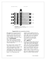
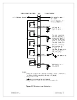
JB1
9
V
0 - 10Vdc
KV Ref.
KV Com
V
mA Com
mA Ref.
0 - 10Vdc
V
Pwr Limit Com (OL Com)
Pwr Limit (OL Ref)
0 - 10Vdc
V
Filament Current Limit Com.
Filament Current Limit
0 - 10Vdc
3) Vin must be referenced to chassis common potential or within ± 1V of ground potential.
2) Zin>10Meg
1) Input Instrumentation amplifiers are AMP-02EP.
4) All signals 0-10Vdc = 0 - 100% of specified outputs.
5) Relay coil Z = 178
Ω.
NOTES:
Ω.
Customer Interface
High Voltage Power Supply
Figure 3.3
Remote programming interface
Other digital status signals provided on
the DF/FF series should be interfaced
using opto-isolators. If possible, analog
signals should be isolated via analog
isolation amplifiers. All interface cables
should be properly shielded. All power
supply signals should be referenced to the
power supply chassis ground. Spellman
application engineers are available to
assist in interface circuitry design.
3.2.1 PROGRAMMING:
Allows remote adjustment of the tube
voltage, tube current, filament current
limit, and maximum tube power limit, via
external voltage source.
For remote program, a positive voltage
source from 0 to 10V = 0-100%, is
applied to the appropriate terminals on the
rear panel 50-pin D connector. By
adjusting the voltage source from 0 volts
(zero output) to 10 volts (full rated output)
the desired output can be selected. See
Figure 3.3 for wiring diagram and
specifications for remote program
interface requirements.
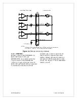
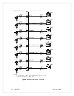
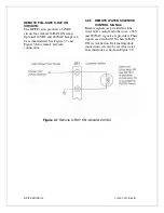
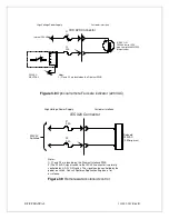
3.2.2 MONITOR:
Test points are made available at the rear
50-pin connector from monitoring tube
voltage, tube current and tube filament
current. Also, tube voltage programming
and tube current programming readback
signals are provided. The test points are
always positive regardless of the output
polarity, where 0 to 10V = 0-100% of
output. Accuracy is within
±
0.5%. All test
points have output impedance at 1Kohm.
Figure 3.4 for remote monitor interface.
Summary of Contents for X3645
Page 1: ...DF FF MANUAL 1 118002 001 Rev B ...
Page 2: ...DF FF MANUAL 2 118002 001 Rev B ...
Page 28: ...DF FF MANUAL 118002 001 Rev B ...
Page 29: ...DF FF MANUAL 118002 001 Rev B ...
Page 30: ...DF FF MANUAL 118002 001 Rev B ...
Page 31: ...DF FF MANUAL 118002 001 Rev B ...
Page 32: ...DF FF MANUAL 118002 001 Rev B ...
Page 33: ...DF FF MANUAL 118002 001 Rev B ...
Page 34: ...DF FF MANUAL 118002 001 Rev B ...
Page 35: ...DF FF MANUAL 118002 001 Rev B ...
Page 36: ...DF FF MANUAL 118002 001 Rev B ...
Page 37: ...DF FF MANUAL 118002 001 Rev B ...
Page 38: ...DF FF MANUAL 118002 001 Rev B ...
Page 39: ...DF FF MANUAL 118002 001 Rev B ...
Page 40: ...DF FF MANUAL 118002 001 Rev B ...


