www.spacelabshealthcare.com
4 - 1 3
9 1 3 9 0
Q U B E
M
A I N T E N A N C E
•
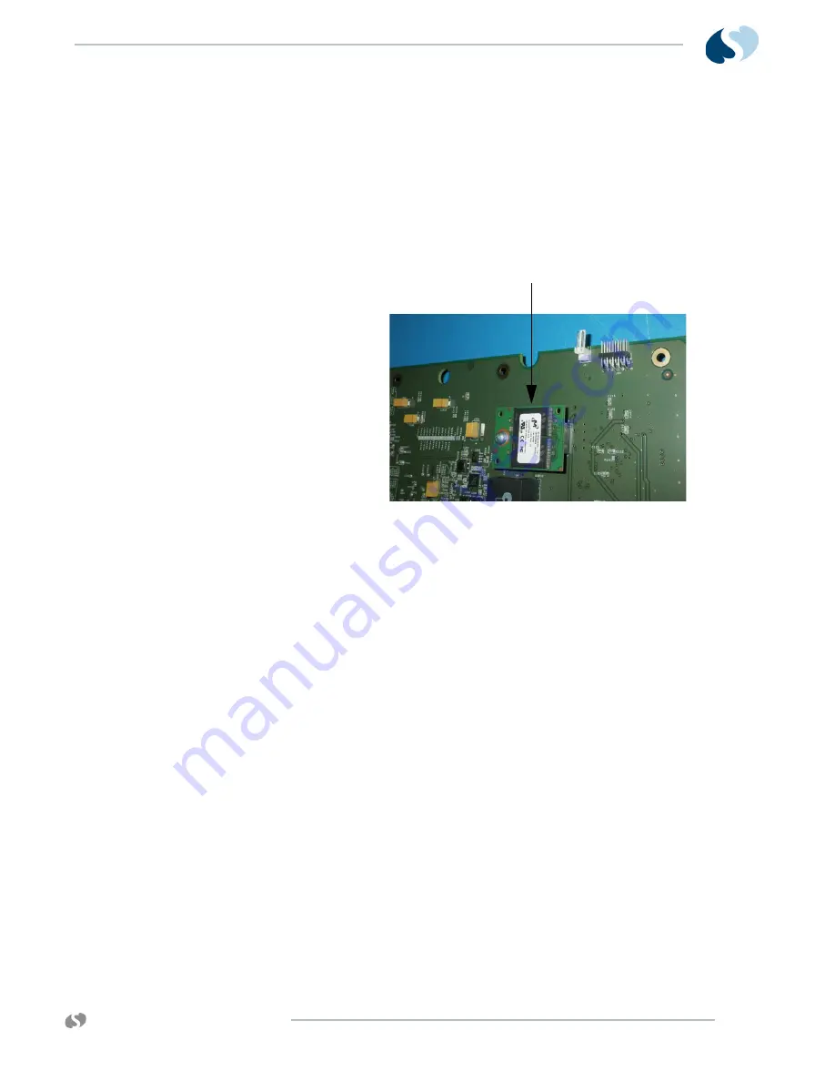
The CPU PCBA contains a USB flash drive PCBA that stores
user-created Custom Trends, as well as Citrix certificates
required for the DNA feature.
•
Reformat the new USB flash drive as part of the CPU
replacement procedure.
•
When you replace the CPU PCBA, Spacelabs Healthcare
recommends that you transfer the old USB flash drive to the
new CPU PCBA.
Figure 4-7 USB Flash Drive
10
Connect speaker cable to P070 port. Connect the fan cable to J8
Port.
11
Install the new CPU onto the chassis. Connect to the battery,
monitor dock, and interface PCBs.
12
Make sure that the speaker and fan cables are not pinched.
13
Use the 12 screws removed in
on page 4-12 to secure the
CPU to the main chassis.
14
Reinstall the wireless adaptor PCB. Reconnect the two antenna
cables if applicable.
15
Place the monitor upright, as shown in
16
Position the bezel assembly as shown in
17
Connect cable 175-1855-xx Com4 to J941 (CPU).
18
Connect cable Center Video Port 175-1858-xx to J40 (CPU).
19
Connect cable 175-1856-xx to J261 (CPU).
20
Connect cable 175-1857-xx Com1 to J50 (CPU).
21
Move the bezel into position. Place the monitor face-down on a
stable, padded surface. To attach the bezel assembly to the rear
enclosure again, use the original screws and finishing plugs
(Refer to
Note:
Options B and C do not have finishing plugs.
USB Card
Summary of Contents for qube 91390
Page 1: ...S E R V I C E M A N U A L 070 2451 01 Rev F www spacelabshealthcare com October 2014 91390...
Page 24: ...www spacelabshealthcare com 1 18 91390 Q U BE I NT R O D U C T IO N...
Page 42: ...www spacelabshealthcare com 2 1 8 91390 Q U BE SE TU P...
Page 54: ...www spacelabshealthcare com 3 1 2 91390 Q U BE T H EO R Y...
Page 90: ...www spacelabshealthcare com 4 3 6 91390 Q U BE M AI N T E N A NC E...
Page 120: ...www spacelabshealthcare com 5 3 0 91390 Q U BE TRO U B L E S H O O T IN G...
Page 160: ...www spacelabshealthcare com B 2 0 91390 Q U BE AP P E N D IX B SY M B O LS...


