


– 7 –
Split Inverter Air-to-Water Heat Pump
Water System
Water System Design
Each SIS Heat Pump has a recommended flow that should be
maintained during all times of operation. For the SIS-060, the
recommended flow is 12GPM at which the head loss is 25ft W.C,
11PSI or 73kPa. This head loss value is based upon pure water,
see appendix for multipliers to correct for various concentrations of
anti-freeze solution.
Note: these are the recommended flow values. Should the flow drop
significantly below this value, the heat pump will shut down and
show a flow error code on the display. This is not an indication of
a fault in the heat pump, but rather points to insufficient pump or
plumbing capacity, or air trapped within the system.
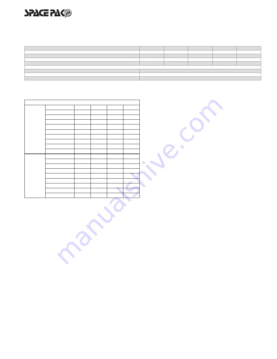
Piping Pressure Losses*
Pressure Drop, Ft H2O/100ft*
Pex
Pipe
Flow Rate GPM
1"
1-1/4"
1-1/2"
2"
6
5.5
1.7
-
-
7
7.2
2.5
1.5
-
8
9.1
3.4
1.8
-
9
11.1
4.3
2.1
0.5
10
13.4
5.2
2.4
0.6
11
15.9
6.2
2.8
0.7
12
18.5
7.2
3.2
0.9
14
-
9.4
4.2
1.2
16
-
11.8
5.4
1.6
Copper
Pipe
(Type L)
6
1.0
-
-
-
7
1.4
0.5
-
-
8
1.8
0.7
-
-
9
2.2
0.8
0.3
-
10
2.7
1.0
0.4
-
11
3.2
1.2
0.5
0.1
12
3.8
1.4
0.6
0.1
14
-
1.8
0.8
0.2
16
-
-
1.0
0.3
*Remember to check the CV rating of your fittings and valves to
make sure you're getting the required flow through the equipment.
Table 2
Table 1 SIS Glycol Concentrations (10% Minimum, 35% Maximum)
Propylene Glycol (concentration by volume)
10%
20%
25%
30%
35%
Min. temp of burst protection
22°F/-5.6°C 11°F/-11.7°C -1°F/-18.3°C -18°F/-27.8°C -46°F/-43.3°C
Capacity Multiplier
0.99
0.98
0.97
0.96
0.94
Pressure Drop Multiplier (Cooling)
1.1
1.2
1.27
1.34
1.42
Pressure Drop Multiplier (Heating)
1.1
1.2
1.27
1.34
1.4
Minimum Expansion Volume/System Volume
Heating and Cooling
1 gallon expansion per 15 gallons system volume
Heating only, HP Only
1 gallon expansion per 20 gallons system volume
Heating Only, with Boiler
1 gallon expansion per 15 gallons system volume
System Volume and Expansion Volume
To ensure smooth temperature control and minimize cycling of
refrigeration system, all installations must have total circulating
volumes equal to or greater than 7.5 gallons per nominal ton of
the unit performance at minimum capacity (The greater of either
heating or cooling produced). In other words, in the case of a five ton
heat pump with 3 to 1 turndown (0.33x rated capacity) the minimum
total system volume is 5x0.33x7.5=12.5 gal. Multiple heat pump
installations that are operating in a staged configuration follow the
same rule, so that only a single heat pump tonnage needs to be
considered. Additionally, the system requires an expansion volume
(air) to compensate for the change in volume of the glycol mixture
as it heats and cools, see Table 1 for expansion volume.
A typical multiple heat pump installation may actually have a volume
far greater than the minimum required, and it is this entire volume
that must be considered when sizing the expansion tank.
Note that the nominal expansion tank volume is not the same as the
expansion volume. If the actual air volume is not published, consider
it to be no more than half the nominal volume.
As an example,
a five ton nominal heat pump operating down
to 33% capacity, used for both heating and cooling, requires
a minimum of 12.5 gallons of circulated system volume. A 13
gallon buffer tank is selected for best operation.
When the system installation is complete, the total volume
including the heat pump, buffer tank, and all plumbing is 18
gallons. (Note: the expansion tank, no matter how large, is not
considered circulated volume).
According to the chart above, the minimum
acceptance volume
of the expansion tank must be at least 18/15, or 1.2 gallons.
If the acceptance volume is not specified, assume it is no greater
than 50% of the total tank volume.
Therefore in the case of this example, the system would require
a minimum tank size of 2.4 gallons. As it is unlikely to find this
specific size.
Always be sure to round up, so a tank of 3 gallons total volume,
or larger, would be appropriate.
Air Separator and Relief Valve
Locate at least one high efficiency air separator as shown in the
piping to remove any air from the system. Install appropriately
rated pressure relief valve common to the hydronic system.