background image

– 5 –

3. EEPROM INITIALIZATION AND DISCHARGING THE BACKUP CAPACITOR

3-1. NV-RAM (EEPROM) Initialization Clear the EEPROM Using the TEST Button on the JIG Remote Controller

1) Plug the VCR into the mains.

Switch on the VCR by pressing (

ON/STANDBY

) on the remote controller.

2) Press (

TEST

) button on the JIG remote controller and released.

3) Within 2 seconds, press the (

CLEAR

) button on the remote controller.

Result:

The EEPROM will be cleared.

4) During the clearing, the “

TEST

” indication flashes on the front of the VCR.

The process will finish after a few seconds.(2-3 seconds)

5) After exiting the display “

TEST

” to normal display.

6) Press the (

ON/STANDBY

) button to switch off the VCR.

7) Disconnect the power supply the VCR.

It is important that you make sure ;

Do not plug the VCR into the mains after clearing EEPROM to ensure that Auto set up procedure works correctry for end users.

3-2. NV-RAM (EEPROM) Initialization Clear the EEPROM without Using the TEST Button on the JIG Remote Controller

1) Plug the VCR into the mains.

Switch on the VCR by pressing (

ON/STANDBY

) on the remote controller.

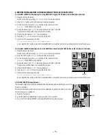
2) Press the TACT switch (

SW718

) on the main PCB and released.

3) Within 2 seconds, press the (

CLEAR

) button on the remote controller.

Result:

The EEPROM will be cleared.

4) During the clearing, the “

TEST

” indication flashes on the front of the VCR.

The process will finish after a few seconds.(2-3 seconds)

5) After exiting the display “

TEST

” to normal display.

6) Press the (

ON/STANDBY

) button to switch off the VCR.

7) Disconnect the power supply the VCR.

It is important that you make sure ;

Do not plug the VCR into the mains after clearing EEPROM to ensure that Auto set up procedure works correctry for end users.

3-3. MICOM RESET (Backup Release)

The automatic adjustment cannot be executed unless the backup battery is discharged even if the

memory is initialized.

Release the backup power as follows only when the adjustment is going to be mode in an ealier

time after the power is turned off.

1) Open the Top cabinet.

2) Short the R692 to TU Shield GND for a few seconds. (1 or 2 seconds)

3) Now the VCR all cleared EEPROM and reseted MICOM same as factory pre-set.

R692

SW718

Summary of Contents for SLV-SE210B

Page 1: ...layback MESECAM SLV SE210B SE210D SX110B SX110D 23 39 mm s recording playback LP PAL SLV SE210G 11 70 mm s recording playback NTSC SLV SE210G 16 67 mm s playback only Maximum recording playback time 10 hrs in LP mode with E300 tape SLV SE210G 5 hrs in SP mode with E300 tape Rewind time Approx 60 sec with E180 tape Inputs and outputs AV1 EURO AV 21 pin Video input pin 20 Audio input pins 2 and 6 Vi...

Page 2: ...not exceed 0 5mA 500 microampers Leakage current can be measured by any one of three methods 1 A commercial leakage tester such as Simpson 229 or RCA WT 540A Follow the manufactures instructions to use these instruments 2 A battery operated AC milliammerter The Data Precision 245 digital multimeter is suitable for this job 3 Measuring the voltage drop across a resistor by means of a VOM or battery...

Page 3: ...searching at various speeds 1 9 Setting the recording duration time 1 10 Checking changing cancelling timer settings 1 10 Adjusting the picture 1 10 Changing menu options 1 11 Editing with another VCR 1 11 Additional Information Troubleshooting 1 12 2 DISASSEMBLY 2 1 Cabinet Top 2 1 2 2 Cover Bottom 2 1 2 3 Ass y Panel Front 2 2 2 4 Ass y MAIN PCB DECK 2 3 2 5 Internal Views 2 4 3 PRINTED WIRING B...

Page 4: ...the Gear Worm Œ clockwise in the direction of arrow with screw driver See Fig 2 Other method Remove the screw of Motor Load Ass y Separate the Motor Load Ass y 2 When Slider S T are approached in the position of unloading rotate holder Clutch counterclockwise after inserting screw driver in the hole of frame s bottom in order to wind the unwiunded tape Refer to Fig 3 If you rotate Gear Worm Œ cont...

Page 5: ...e Controller 1 Plug the VCR into the mains Switch on the VCR by pressing ON STANDBY on the remote controller 2 Press the TACT switch SW718 on the main PCB and released 3 Within 2 seconds press the CLEAR button on the remote controller Result The EEPROM will be cleared 4 During the clearing the TEST indication flashes on the front of the VCR The process will finish after a few seconds 2 3 seconds 5...

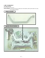
Page 6: ...heck jig Bracket Handling Part No 3 067 793 01 How to use the jig When you want to check the conductor side of the Main board attch the jig first and the turn over the MD Ass y and the Main board BRACKET HANDLING Assembly of Bracket Handling ...

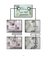
Page 7: ... 7 BRACKET HANDLING Twist ...

Page 8: ... 8 MEMO ...

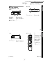
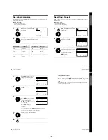
Page 9: ...7 m REW rewind button 27 39 M FF fast forward button 27 39 H PLAY OK button 25 27 1 2 3 4 5 6 7 8 9 0 continued 6 Index to parts and controls Rear panel A8 IN FRONT ANT in front antenna connector 12 13 BMains lead 14 CAV1 EURO AV connector 13 46 D OUT TO TV connector 12 13 1 1 4 Index to parts and controls Getting Started Index to parts and controls Refer to the pages indicated in parentheses for ...

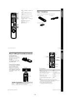
Page 10: ...by mode 1 Select an input source aerial in or line in t TV VIDEO Select the TV s programme position Programme number buttons PROG Adjust the volume of the TV 2 Call up the on screen display DISPLAY Switch to from wide mode of a Sony wide TV WIDE 1 2 3 4 5 6 7 8 9 0 Programme number buttons WIDE DISPLAY PROG 1 t TV VIDEO 2 10 Setting up the remote commander Step 2 Setting up the remote commander In...

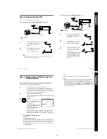
Page 11: ...ect the mains lead again If you want to use the Auto Set Up function again press MENU then press M m to highlight INSTALLATION and press OK Press M m to highlight AUTO SET UP then repeat the procedure from step 3 14 Setting up the VCR with the Auto Set Up function Step 4 Setting up the VCR with the Auto Set Up function Before using the VCR for the first time set up the VCR using the Auto Set Up fu...

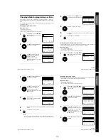
Page 12: ...o 80 press M m repeatedly MENU OK PLAY EXIT SET MENU OK END SELECT AUTO SET UP MANUAL SET UP C H 2 1 VCR OUTPUT CH OK PLAY EXIT MENU CLEAR DELETE SWAPPING OK TV STATION TABLE 5 4 3 2 1 0 0 0 0 3 3 2 2 2 0 9 7 I C L A J D M A K E N B OFF OFF OFF OFF PR CH NAME DEC OK PLAY MENU OK END SELECT MANUAL TUNING PR 5 CH MFT NAME SET EXIT continued Getting Started 19 Presetting channels If the picture is no...

Page 13: ... OK PLAY SET MENU OK END SELECT AUTO SET UP MANUAL SET UP VCR OUTPUT CH EXIT C H 2 1 continued Getting Started 23 Changing disabling programme positions Changing the station names You can change or enter the station names up to 4 characters The VCR must receive channel information for station names to appear automatically Before you start Turn on the VCR and the TV Set the TV to the video channel ...

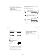
Page 14: ...r button locations Additional tasks To use the time counter Press CLEAR at the point on the tape that you want to find later The counter in the display window resets to 00 00 Search for the point afterwards by referring to the counter To display the counter on the TV screen press DISPLAY 1 Turn on your TV and set it to the video channel 2 Insert a tape The VCR turns on and starts playing automatic...

Page 15: ...n the counting cycles of the two video systems When you insert a non standard commercially available tape the remaining time may not be correct The remaining time is intended for rough measurement only About 30 seconds after the tape begins playback the tape remaining time will be displayed 30 Recording TV programmes To check the remaining time Press DISPLAY With the display on press COUNTER REMAI...

Page 16: ...ds by for recording To record from another source leave the connected equipment switched on CLEAR OK PLAY INPUT SELECT EXIT SET MENU OK END SELECT PR DAY START STOP V P FRI SEP 8 2 1 8 3 0 3 5 S A 2 9 1 9 0 0 2 0 0 LP 0 OK PLAY EXIT SET MENU OK END SELECT PR DAY START STOP V P ON FRI SEP 8 2 1 8 3 0 3 5 S A 2 9 1 9 0 0 2 0 0 LP 0 MENU continued 35 Recording TV programmes using the VIDEO Plus syste...

Page 17: ...the menu 4 Press 1 to turn off the VCR The indicator appears in the display window and the VCR stands by for recording To record from another leave the connected equipment switched on OK PLAY INPUT SELECT EXIT SET MENU OK END SELECT PR DAY START STOP V P FRI SEP 8 2 1 8 3 0 3 5 MENU continued 39 Playing searching at various speeds Additional Operations Additional Operations Playing searching at va...

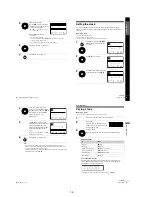
Page 18: ...s M m to reset it To cancel the setting press CLEAR 5 Press MENU to exit the menu If any settings remain turn off the VCR to return to recording standby SET MENU OK END SELECT PR DAY START STOP V P FRI SEP 8 2 1 8 3 0 3 5 S A 1 9 0 0 2 0 0 0 2 9 S A 2 9 2 9 2 1 0 0 2 3 0 1 3 0 S A 6 1 2 0 0 1 3 0 3 EXIT LP LP SP 2 9 2 9 6 LP LP SP EXIT SET MENU OK END SELECT PR DAY START STOP V P FRI SEP 8 2 1 8 3...

Page 19: ...ption Set this option to VPS PDC DEFAULT OFF to deactivate the VPS PDC function ON to activate it VIDEOPLUS EXTEND OFF to deactivate the VIDEOPLUS Extend function 10 20 30 60 minutes to extend the time of the VIDEO Plus setting by the selected amount of time AUTO POWER OFF OFF to deactivate the Auto Power Off function 2HOUR 3HOUR to turn the VCR off automatically if no signal is received and you d...

Page 20: ...nt TV reception is poor Make sure the aerial cable is connected securely Adjust the TV aerial The tape starts playing as soon as it is inserted The safety tab has been removed To record on this tape cover the tab hole see page 30 The tape is ejected when you press z REC The safety tab has been removed To record on this tape cover the tab hole see page 30 Nothing happens when you press z REC Make s...

Page 21: ...X110A SX110B 2 1 Cabinet Top CABINET TOP Lift up the Cabinet Top in the direction of arrow by releasing the Hook Œ 2 SCREWS Fig 2 1 Cabinet Top 2 2 Cover Bottom Fig 2 2 Cover Bottom Œ RELEASE 2 SNAPFITS Lift up the Bottom Cover in the direction of arrow ...

Page 22: ...2 2 2 3 Ass y Panel Front Fig 2 3 Ass y Panel Front Œ RELEASE 4 HOOKS RELEASE 3 HOOKS TOP VIEW ASS Y PANEL FRONT BOTTOM VIEW ...

Page 23: ... CABLE ASS Y DECK ˆ FLAT CABLE Ø CONNECTOR RELEASE HOOK ˇ 3 SCREWS PUSH 2 5 Internal Views CYLINDER Assembly Drum 1 763 706 11 SE210B SE210D SX110A SX110B 1 763 707 11 SE210G ACE HEAD Assembly 1 500 698 11 LOADING MOTOR Assembly 1 763 704 11 CAPSTAN MOTOR 1 763 703 11 2 3 2 4E Top View Bottom View ...

Page 24: ...SLV SE210B SE210D SE210G SX110A SX110B SECTION 3 PRINTED WIRING BOARDS 3 1 3 2 3 1 Main PCB COMPONENT SIDE ...

Page 25: ...SLV SE210B SE210D SE210G SX110A SX110B CONDUCTOR SIDE 3 3 3 4E ...

Page 26: ...SLV SE210B SE210D SE210G SX110A SX110B SECTION 4 SCHEMATIC DIAGRAMS Block Identification of Main PCB Component Side Conductor Side 4 1 4 2 ...

Page 27: ...SLV SE210B SE210D SE210G SX110A SX110B 4 1 S M P S Œ 4 3 4 4 ...

Page 28: ...SLV SE210B SE210D SE210G SX110A SX110B 4 2 Power 4 5 4 6 ...

Page 29: ...SLV SE210B SE210D SE210G SX110A SX110B 4 3 System Control Servo ˇ ˆ 4 7 4 8 ...

Page 30: ...SLV SE210B SE210D SE210G SX110A SX110B Æ Ú Ò Ô ı 4 4 Audio Video 4 9 4 10 ...

Page 31: ...SLV SE210B SE210D SE210G SX110A SX110B 4 5 TM Block 4 11 4 12 ...

Page 32: ...SLV SE210B SE210D SE210G SX110A SX110B 4 6 OSD VPS PDC 4 13 4 14 ...

Page 33: ...SLV SE210B SE210D SE210G SX110A SX110B 4 7 SECAM SLV SE210B SX110B model 4 15 4 16 ...

Page 34: ...SLV SE210B SE210D SE210G SX110A SX110B 4 8 Input Output 2 Scart Jack 4 17 4 18 ...

Page 35: ...SLV SE210B SE210D SE210G SX110A SX110B 4 9 Input Output 1 Scart Jack 4 19 4 20 ...

Page 36: ... 24 REC 1 2Vp p IC301 20 PB REC 600mVp p IC301 90 REC 4Vp p Ò IC301 29 PB 2 2Vp p Ú IC301 46 PB 400mVp p IC301 96 PB REC 1Vp p Æ IC301 74 PB 300mVp p IC601 9 PB 5 1Vp p IC601 18 PB 4Vp p ˆ IC601 10 PB 5 1Vp p IC601 100 PB 4 3Vp p Ø CN604 6 PB 5 1Vp p IC610 8 PB 5 1V Q1SR01 COLLECTOR POWER ON 400Vp p S M P S BLOCK TM BLOCK O S D BLOCK SYSTEM CONTROL SERVO BLOCK AUDIO VIDEO BLOCK 4 21 4 22 ...

Page 37: ...SLV SE210B SE210D SE210G SX110A SX110B 4 23 4 24E ...

Page 38: ...ure to adjust the X Point and Head switching adjustment 4 How to adjustment Press the SW718 button on Main PCB to set the adjustment mode If the corresponding adjustment button is pressed the adjustment is performed automatically If the adjustment is completed be sure to turn the power off 5 1 1 Location of adjustment button of remote control Fig 5 1 1 2 3 4 5 6 7 8 9 0 X Point Tracking Center Adj...

Page 39: ...d Position X Point Adjustment See the 5 2 1 d ACE Head Position X Point Adjustment on page 5 2 of the Mechanical Manual 1 Playback the alignment tape Color bar 2 Press the SW718 button on Main PCB to set the adjustment mode See Fig 5 2 3 Press the 5 button of remote control then adjust ment is operated automatically See Fig 5 1 4 Connect the CH 1 probe to TP301 Envelope the CH 2 probe to TP602 H D...

Page 40: ...leted 6 Turn the Power off 1 NVRAM Option is adjusted at production line basically 2 In case Micom IC601 and NVRAM IC605 EEPROM is replaced be sure to set the corresponding option number of the reqaired model If the option is not set the unit is not operated 01 02 03 04 05 06 07 08 09 10 11 12 13 14 15 16 17 18 19 20 21 22 23 24 25 26 27 28 29 30 31 32 33 34 35 36 37 38 39 40 41 42 43 44 45 46 47 ...

Page 41: ...11 SCREW BVTP 4X12 TYPE2 NON SLIT 155 7 685 663 11 SCREW BVTP 4X16 TYPE2 NON SLIT 157 7 685 548 19 SCREW BTP 3X12 TYPE2 NON SLIT 0200 1 823 023 11 POWER CORD SE210B SE210D SX110A SX110B 0200 1 823 025 11 POWER CORD SE210G CN3A1S 1 823 022 11 CABLE FLAT 6P CN602S 1 823 164 11 CABLE FLAT 7P LD601A 3 067 777 01 HOLDER LED S601A 3 067 776 01 HOLDER SENSOR S602A 3 067 776 01 HOLDER SENSOR TM401B 3 066 ...

Page 42: ... 070 041 01 DAMPER CAPSTAN G001 1 763 706 11 ASSY CYLINDER PAL SE210B SE210D SX110A SX110B G001 1 763 707 11 ASSY CYLINDER PAL SE210G G060 7 682 647 01 SCREW ASSY MACH PS 3X6 G070 3 067 796 01 PLATE GROUND DECK G480 1 500 698 11 HEAD ACE ASS G510 7 621 759 35 SCREW ASSY TAPT PSW 2 6X5Y G520 3 067 779 01 LEVER 9 GUIDE ASSY G527 3 067 780 01 SPRING 9 GUIDE G546 3 067 787 01 LEVER FL DOOR G555 3 067 ...

Page 43: ...t supplied not supplied not supplied not supplied not supplied not supplied 6 3 Ref No Part No Description Remarks Ref No Part No Description Remarks B560 1 763 703 11 MOTOR CAPSTAN B570 7 685 133 11 SCREW P 2 6X6 TYPE2 G542 3 067 790 01 BELT PULLEY 6 1 3 Mechanical Parts Bottom Side ...

Page 44: ...165 561 11 CERAMIC MLC AXIAL 180pF 10 50V C306 1 165 562 11 CERAMIC MLC AXIAL 330pF 10 50V C307C 1 163 231 11 CERAMIC CHIP 15pF 5 50V C308C 1 163 021 11 CERAMIC CHIP 0 01uF 10 50V C309 1 126 458 61 ELECT 1uF 20 50V C310 1 126 109 11 ELECT 10uF 20 16V C311 1 126 435 71 ELECT 22uF 20 16V C313C 1 163 275 11 CERAMIC CHIP 0 001uF 10 50V C314 1 126 456 11 ELECT 0 47uF 20 50V C315 1 126 109 11 ELECT 10uF...

Page 45: ...V C404 1 126 958 11 ELECT 0 33uF 20 50V C405 1 119 943 11 ELECT 47uF 20 50V C406C 1 163 033 11 CERAMIC CHIP 0 022uF 10 50V C407 1 126 437 11 ELECT 47uF 16V SE210D SE210G SX110A C410 1 165 563 11 CERAMIC MLC AXIAL 0 1uF 80 20 50V C601 1 126 437 11 ELECT 47uF 20 16V C602C 1 163 033 11 CERAMIC CHIP 0 022uF 10 50V C603C 1 163 017 11 CERAMIC CHIP 0 0047uF 10 50V C604C 1 163 017 11 CERAMIC CHIP 0 0047uF...

Page 46: ...HIP 330pF 5 50V SE210B SE210D C837C 1 163 263 11 CERAMIC CHIP 330pF 5 50V C842C 1 163 263 11 CERAMIC CHIP 330pF 5 50V SE210B SE210D C845C 1 164 690 11 CERAMIC CHIP 0 0022uF 10 50V C850 1 161 330 11 CERAMIC MLC AXIAL 0 01uF 30 16V SE210B SE210D C852C 1 165 319 11 CERAMIC CHIP 1uF 80 20 16V SE210B SE210D C854C 1 165 319 11 CERAMIC CHIP 1uF 80 20 16V SE210B SE210D CONNECTOR CN1SS1 1 815 692 11 CONNEC...

Page 47: ...ISTOR KSC2328A Y Q1P102 1 804 424 11 TRANSISTOR KSC2328A Y Q1P104 1 804 481 11 TRANSISTOR STB1277 Q1P105 1 804 427 11 TRANSISTOR KSR1001 Q1SR01 1 804 425 11 TRANSISTOR 2SC4517A Q1SR02 1 804 422 11 TRANSISTOR KTC3203 Y Q302 1 804 420 11 TRANSISTOR KSA733 Q303 1 804 421 11 TRANSISTOR KSC945 Q304 1 804 421 11 TRANSISTOR KSC945 Q307 1 804 428 11 TRANSISTOR KSR1004 SE210G Q308 1 804 421 11 TRANSISTOR K...

Page 48: ...180 5 1 10W R3A07C 1 218 764 11 RES CHIP 330K 5 1 10W R3A08C 1 216 677 11 RES CHIP 12K 5 1 10W R3A09C 1 216 669 11 RES CHIP 5 6K 5 1 10W R3A10 1 247 831 11 CARBON 1K 5 1 8W R3A11C 1 216 657 11 RES CHIP 1 8K 5 1 10W R3A12C 1 216 611 11 RES CHIP 2 2 5 1 10W R3A13C 1 216 643 11 RES CHIP 470 5 1 10W R3A14 1 247 863 11 CARBON 22K 5 1 8W R3A16 1 247 855 11 CARBON 10K 5 1 8W R3A17 1 247 845 11 CARBON 3 9...

Page 49: ...1 247 807 11 CARBON 100 5 1 8W SE210B SX110B R698C 1 216 675 11 RES CHIP 10K 5 1 10W R699C 1 216 675 11 RES CHIP 10K 5 1 10W R6P01C 1 216 627 11 RES CHIP 100 0 5 1 10W SE210B SE210D R6P02 1 247 807 11 CARBON 100 5 1 8W SE210B SE210D R6P03C 1 216 661 11 RES CHIP 2 7K 5 1 10W SE210B SE210D R6P04C 1 216 675 11 RES CHIP 10K 5 1 10W SE210B SE210D R6P05 1 247 855 11 CARBON 10K 5 1 8W R6P06C 1 216 669 11...

Page 50: ...01 1 795 330 11 VIBRATOR CRYSTAL 4 433619MHZ XT601 1 795 332 11 VIBRATOR CRYSTAL 32 768KHz XT602 1 795 331 11 VIBRATOR CRYSTAL 8MHz ZENER DIODE ZD1P02 1 804 416 11 DIODE ZENER MTZJ5 1B ZD1P04 1 804 417 11 DIODE ZENER MTZJ9 1B ZD1SS1 1 804 415 11 DIODE ZENER UZP43B ZD401 1 804 414 11 DIODE ZENER UZP33B ZD801 1 804 418 11 DIODE ZENER MTZJ12B ZD802 1 804 418 11 DIODE ZENER MTZJ12B SE210B SE210D MISCE...

Page 51: ...6 11E Ref No Part No Description Remarks 3 066 349 31 MANUAL INSTRUCTION FINNISH SE210D SX110A 3 709 433 01 COVER REMOTE CONTROL BATTERY FOR RMT ...

Page 52: ... 68 Sony Corporation Network Entertainment Group SLV SE210B SE210D SE210G SX110A SX110B 9 921 793 11 2001C1600 1 2001 3 Published by Quality Assurance Dept ...

Reviews: