– 4 –
SERVICE NOTE
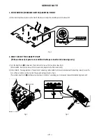
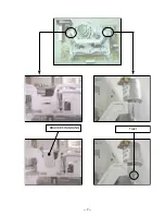
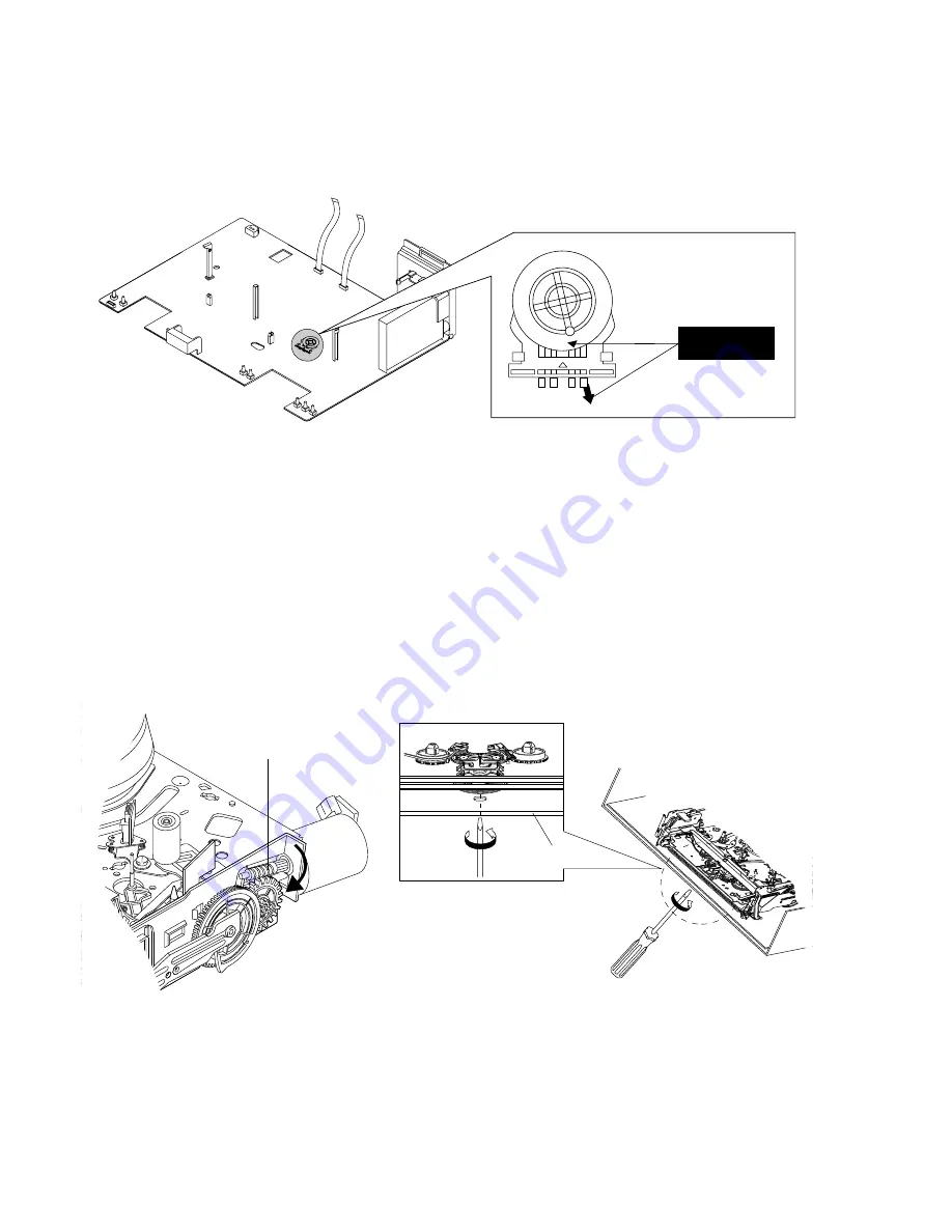
1. MODE SWITCH (PROGRAM SWITCH) ASSEMBLY POINT
1) When installing the ass’y deck on the Main PCB, be sure to align the assembly point of mode switch.
ASSEMBLY POINT
(ALIGN TWO ARROWS)
Fig. 1
2. HOW TO EJECT THE CASSETTE TAPE
(If the unit does not operate on condition that tape is inserted into housing ass’y)
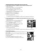
1) Turn the Gear Worm
Œ
clockwise in the direction of arrow with screw driver. (See Fig. 2)
(Other method ; Remove the screw of Motor Load Ass’y, Separate the Motor Load Ass’y)
2) When Slider S, T are approached in the position of unloading, rotate holder Clutch counterclockwise after inserting screw driver in the
hole of frame’s bottom in order to wind the unwiunded tape. (Refer to Fig. 3)
(If you rotate Gear Worm
Œ
continuously when tape is in state of unwinding, you may cause a tape contamination by grease and
Fig. 2
Fig. 3
Œ
GEAR WORM
FRAME
Summary of Contents for SLV-SE210B
Page 7: ... 7 BRACKET HANDLING Twist ...
Page 8: ... 8 MEMO ...
Page 25: ...SLV SE210B SE210D SE210G SX110A SX110B CONDUCTOR SIDE 3 3 3 4E ...
Page 27: ...SLV SE210B SE210D SE210G SX110A SX110B 4 1 S M P S Π4 3 4 4 ...
Page 28: ...SLV SE210B SE210D SE210G SX110A SX110B 4 2 Power 4 5 4 6 ...
Page 29: ...SLV SE210B SE210D SE210G SX110A SX110B 4 3 System Control Servo ˇ ˆ 4 7 4 8 ...
Page 30: ...SLV SE210B SE210D SE210G SX110A SX110B Æ Ú Ò Ô ı 4 4 Audio Video 4 9 4 10 ...
Page 31: ...SLV SE210B SE210D SE210G SX110A SX110B 4 5 TM Block 4 11 4 12 ...
Page 32: ...SLV SE210B SE210D SE210G SX110A SX110B 4 6 OSD VPS PDC 4 13 4 14 ...
Page 33: ...SLV SE210B SE210D SE210G SX110A SX110B 4 7 SECAM SLV SE210B SX110B model 4 15 4 16 ...
Page 34: ...SLV SE210B SE210D SE210G SX110A SX110B 4 8 Input Output 2 Scart Jack 4 17 4 18 ...
Page 35: ...SLV SE210B SE210D SE210G SX110A SX110B 4 9 Input Output 1 Scart Jack 4 19 4 20 ...
Page 37: ...SLV SE210B SE210D SE210G SX110A SX110B 4 23 4 24E ...


