


2-12
1
SPRING TENTION LEVER
2
LEVER TENTION ASS`Y
3
BAND BRAKE ASS`Y
STOPPER
MARK[B]
"A"
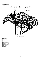
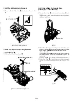
2-4-11 Lever Pinch Drive,
Lever Tension Drive Removal
1) Remove the Lever Pinch Drive
1
, Lever Tension Drive
2
.
Fig. 2-23 Lever Pinch Drive,
Lever Tension Drive Removal
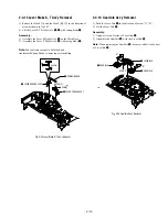
2-4-12 Lever Tension Ass’y,
Band Brake Ass’y Removal
1) Remove the Lever Brake S Ass’y (Refer to Fig 2-25).
2) Remove the Spring Tension Lever
1
.
3) Rotate stopper of Main Base in the direction of arrow “A”.
4) Lift the Lever Tension Ass’y
2
& Band brake Ass’y
3
.
Note:
1) When replacing the Lever Tension Ass’y
2
, be sure to apply Grease
on the post,
2) Take care not to touch stain on the felt side, and not to be folder
and broken Band brake Ass’y
3) After Lever Tension Ass’y seated, Rotate stopper of Main Base to
the Mark[B].
Fig. 2-24 Lever Tension Ass’y,
Band Brake Ass’y Removal
1
LEVER PINCH DRIVE
2
LEVER TENSION DRIVE
Summary of Contents for RMT-V501C
Page 10: ... 10 MEMO ...
Page 67: ...3 BLOCK DIAGRAM 3 2 3 1 SLV D350P D550P ...
Page 68: ...3 4E MEMO ...
Page 70: ...4 3 4 4 4 1 VCR MAIN FUNCTION TIMER COMPONENT SIDE ...
Page 71: ...4 6 4 5 CONDUCTOR SIDE ...
Page 72: ...4 7 4 8 COMPONENT SIDE CONDUCTOR SIDE 4 2 DVD MAIN ...
Page 73: ...4 10 4 9 4 3 DIAL TIMER SLV D550P Only COMPONENT SIDE CONDUCTOR SIDE ...
Page 74: ...4 12E MEMO ...
Page 76: ... BLOCK IDENTIFICATION OF MAIN PCB 5 3 5 4 Component Side Conductor Side VCR MAIN PCB ...
Page 77: ...5 1 S M P S 5 6 5 5 ...
Page 78: ...5 2 POWER DRIVE 5 7 5 8 ...
Page 79: ...5 3 LOGIC FUNCTION TIMER 5 10 5 9 ...
Page 80: ...5 4 A V 5 11 5 12 ...
Page 81: ...5 5 Hi Fi MTS 5 14 5 13 ...
Page 82: ...5 6 INPUT OUTPUT 5 15 5 16 ...
Page 83: ...5 7 DVD 5 18 5 17 ...
Page 84: ...MEMO 5 20E ...
Page 112: ...7 18E MEMO ...