


2-7
2-4 VCR DECK
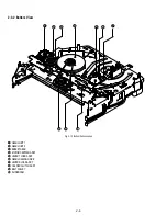
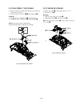
2-4-1 Holder FL Cassette Ass’y Removal
1) Pull the Holder FL Cassette Ass’y
1
to the eject position.
2) Pull the Holder FL Cassette Ass’y
1
as grasping the Holder FL
Cassette Ass’y
1
and Lever FL Cassette-R
2
in the same time to
release hooking from Main Base until the Boss [A] of Holder FL
Cassette Ass’y
1
is taken out from the Rail [B].
3) Lift the Holder FL Cassette Ass’y
1
, in this time, you have to
grasp the Lever FL Cassette-R
2
Continuously until the Holder
FL Cassette Ass’y
1
is taken out completely.
Note:
Be sure to insert Lever FL Cassette-R
2
in the direction of
“A” to prevent separation and breakage of the Lever FL Cassette-
R
2
at disassembling and reassembling.
Fig. 2-11 Holder FL Cassette Ass’y Removal
RAIL [B]
BOSS [A]
2
LEVER FL CASSETTEE -R
"A"
1
HOLDER FL
CASSETTEE ASS'Y
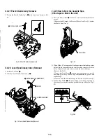
2-4-2 Lever FL Arm Ass’y Removal
1) Push the hole “A” in the direction of arrow “B” use the pin.(about
Dia. 2.5)
2) Pull out the Lever FL Arm Ass’y
1
from the Boss of Main Base.
3) Remove the Lever FL Arm Ass’y
1
in the direction of arrow “C”.
Fig. 2-12 Lever FL Arm Ass’y Removal
1
LEVER FL ARM ASS'Y
"C"
"B"
PIN
HOLE "A"
Summary of Contents for RMT-V501C
Page 10: ... 10 MEMO ...
Page 67: ...3 BLOCK DIAGRAM 3 2 3 1 SLV D350P D550P ...
Page 68: ...3 4E MEMO ...
Page 70: ...4 3 4 4 4 1 VCR MAIN FUNCTION TIMER COMPONENT SIDE ...
Page 71: ...4 6 4 5 CONDUCTOR SIDE ...
Page 72: ...4 7 4 8 COMPONENT SIDE CONDUCTOR SIDE 4 2 DVD MAIN ...
Page 73: ...4 10 4 9 4 3 DIAL TIMER SLV D550P Only COMPONENT SIDE CONDUCTOR SIDE ...
Page 74: ...4 12E MEMO ...
Page 76: ... BLOCK IDENTIFICATION OF MAIN PCB 5 3 5 4 Component Side Conductor Side VCR MAIN PCB ...
Page 77: ...5 1 S M P S 5 6 5 5 ...
Page 78: ...5 2 POWER DRIVE 5 7 5 8 ...
Page 79: ...5 3 LOGIC FUNCTION TIMER 5 10 5 9 ...
Page 80: ...5 4 A V 5 11 5 12 ...
Page 81: ...5 5 Hi Fi MTS 5 14 5 13 ...
Page 82: ...5 6 INPUT OUTPUT 5 15 5 16 ...
Page 83: ...5 7 DVD 5 18 5 17 ...
Page 84: ...MEMO 5 20E ...
Page 112: ...7 18E MEMO ...