


1-26
109
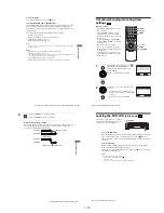
General setup information
Ad
d
itiona
l In
fo
rm
ation
Menu choices
The default settings are indicated in bold print.
4
Press SET UP to exit the menu.
Menu option
Set this option to
Auto Power Off
• “
Off
” to deactivate the Auto Power Off function.
• “1Hr”/“2Hr” to turn the DVD-VCR off automatically if no
signal is received and you do not press any of the buttons
during this time.
RF Output Channel
• “
3CH
” when using channel 3 to receive the VCR signal.
• “4CH” when using channel 4 to receive the VCR signal.
For details, see page 110.
continued
110
General setup information
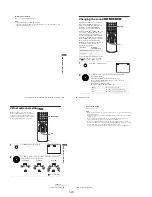
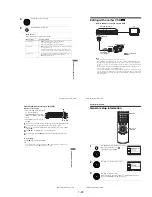
Setting the RF Output channel
When connecting the DVD-VCR to the TV
using only the antenna cable, you must set
the RF Output channel in the “OPTION
SETUP” menu so that the TV can receive the
correct signal from the DVD-VCR.
1
Set the RF Output channel to “3CH” or “4CH” (see page 108 to set the channel),
whichever channel is not used in your area. If both are used, set the switch to
either channel.
2
Press
?
/
1
to turn on the DVD-VCR.
3
Press TV/VIDEO to turn on “VIDEO” in the DVD-VCR’s display window.
4
Press CH +/– to display a channel number in the display window.
Select an active channel number in your area.
5
Turn on your TV and set it to the channel you selected in step 1 (3CH or 4CH).
The channel you selected in step 4 appears on the TV screen. If the channels
change when you press CH +/–, you have made the correct setting.
Whenever you use the DVD-VCR, set the TV to the channel selected in step 1.
TV
C/–
?
/
1
TV/VIDEO
CH +/–
?
/
1
111
General setup information
Ad
d
itiona
l In
fo
rm
ation
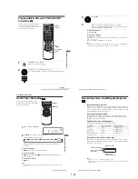
Attaching the external antenna connector
Attaching a VHF/UHF band mixer
When using a 300-ohm twin lead cable for a
VHF/UHF antenna, use an antenna connector
(not supplied) to connect the antenna to the
DVD-VCR.
1
Loosen the screws on the antenna connector.
2
Wind the twin leads around the screws on the antenna connector.
3
Retighten the screws.
When using both a 75-ohm coaxial cable and
a 300-ohm twin lead cable for a VHF/UHF
antenna, use a VHF/UHF band separator/
mixer (not supplied) to connect the antenna
to the DVD-VCR.
1
Loosen the screws on the mixer.
2
Wind the twin leads around the screws on the mixer.
3
Retighten the screws.
4
Connect the 75-ohm coaxial cable to the mixer.
300-ohm twin
lead cable
Antenna
connector
(not supplied)
300-ohm twin
lead cable
VHF/UHF
band
separator/
mixer (not
supplied)
75-ohm coaxial
cable
112
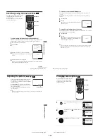
Troubleshooting
Troubleshooting
If you have any questions or problems not covered below, please consult your nearest Sony
dealer. (For customers in USA)
General Troubleshooting
Symptom
Remedy
Po
w
e
r
The
?
/
1
switch does not function.
• Connect the AC power cord securely.
The power is turned on but the DVD-
VCR does not operate.
• Moisture condensation has occurred. Turn the power off,
unplug the AC power cord and leave the DVD-VCR to
dry for over three hours.
Clo
c
k
The clock has stopped and “--:--”
appears in the display window.
• The clock stops if the DVD-VCR is disconnected from
the wall outlet. Reset the clock (and timer).
Ot
he
rs
The remote commander does not
function.
• Make sure you are pointing the remote commander at the
remote sensor on the DVD-VCR.
• Replace all the batteries in the remote commander with
new ones if they are weak.
• Make sure the TV / DVD·VIDEO switch is set correctly.
• Select correctly VIDEO or DVD with the SELECT DVD/
VIDEO button.
The tracking meter does not appear
on the screen.
• The recording condition of the tape is very poor and
tracking cannot be adjusted.
You cannot control other TVs.
• Set your TV’s code number. The code number may
change when you replace the batteries of the remote
commander.
Summary of Contents for RMT-V501C
Page 10: ... 10 MEMO ...
Page 67: ...3 BLOCK DIAGRAM 3 2 3 1 SLV D350P D550P ...
Page 68: ...3 4E MEMO ...
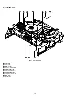
Page 70: ...4 3 4 4 4 1 VCR MAIN FUNCTION TIMER COMPONENT SIDE ...
Page 71: ...4 6 4 5 CONDUCTOR SIDE ...
Page 72: ...4 7 4 8 COMPONENT SIDE CONDUCTOR SIDE 4 2 DVD MAIN ...
Page 73: ...4 10 4 9 4 3 DIAL TIMER SLV D550P Only COMPONENT SIDE CONDUCTOR SIDE ...
Page 74: ...4 12E MEMO ...
Page 76: ... BLOCK IDENTIFICATION OF MAIN PCB 5 3 5 4 Component Side Conductor Side VCR MAIN PCB ...
Page 77: ...5 1 S M P S 5 6 5 5 ...
Page 78: ...5 2 POWER DRIVE 5 7 5 8 ...
Page 79: ...5 3 LOGIC FUNCTION TIMER 5 10 5 9 ...
Page 80: ...5 4 A V 5 11 5 12 ...
Page 81: ...5 5 Hi Fi MTS 5 14 5 13 ...
Page 82: ...5 6 INPUT OUTPUT 5 15 5 16 ...
Page 83: ...5 7 DVD 5 18 5 17 ...
Page 84: ...MEMO 5 20E ...
Page 112: ...7 18E MEMO ...