


1-3
Getti
ng Sta
rted
17
Basic hookups
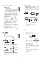
Hookup 2 (Plug and Play)
You have no cable box, or a cable box with only a few
scrambled channels
Recommended use
Use this hookup if you do not have a cable box. Also use this hookup if your cable
system scrambles only a few channels.
What you can do with this hookup
• Record any unscrambled channel by selecting the channel on the VCR
What you cannot do
• Record scrambled channels that require a cable box
Rear of TV
VHF/UHF
VHF
UHF
DVD-VCR
Match the type
of connector
on your TV: A,
B, or C.
For connector
types B and C,
no UHF
connection is
required.
B
C
or
or
Cable box
A
VHF
UHF
Wall
Connect this cable
directly to your TV if
you do not have a
cable box.
continued
18
Basic hookups
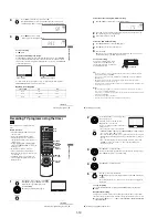
Hookup 2 : DVD-VCR setup
Notes
• If you connect the AC power cord before the antenna connections are completed, the channels
may be incorrectly set. If this happens, see “Step 6 : Presetting channels” on page 26.
• Do not press any buttons on the DVD-VCR or remote commander during Auto preset.
• Auto preset starts automatically only when you plug in the AC power cord for the first time
after you purchase the DVD-VCR.
• Auto preset can be performed by pressing
x
on the unit continuously for 5 seconds or more
with the DVD-VCR power turned off.
Plug the DVD-VCR into an AC outlet.
The DVD-VCR automatically presets the DVD-VCR’s clock and TV channels
when the DVD-VCR is plugged into the AC outlet.
The DVD-VCR starts presetting the
clock and channels.
When Auto preset is completed, the
current time appears in the display
window.
You have now completed DVD-VCR setup.
To change the on-screen display language to French or Spanish, see
“Step 4 : Selecting a language” on page 20.
The clock is set using a time signal provided by some TV channels. If the clock
is incorrect, or “--:--” appears in the display window, see “Using Manual Clock
Set” on page 24.
To add or disable channels manually, see “Presetting/disabling channels
manually” on page 28.
AC power cord
to AC outlet
Getti
ng Sta
rted
19
Basic hookups
Hookup 3
Connecting a cable box with many scrambled channels
Recommended use
Use this hookup if your cable system scrambles all or most channels.
What you can do with this hookup
• Record any channel by selecting the channel on the cable box
What you cannot do
• Record with the cable box turned off
• Record one channel while watching another channel
After you have completed hookup…
After you have completed hookup, plug the DVD-VCR into an AC outlet and see
“Step 4 : Selecting a language” on page 20.
Rear of TV
VHF/UHF
VHF
UHF
DVD-VCR
Match the type of
connector on your
TV: A, B, or C.
For connector
types B and C, no
UHF connection
is required.
B
C
or
or
Cable box
A
VHF
UHF
Wall
to AC outlet
AC power cord
20
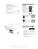
Selecting a language
Step 4 : Selecting a language
You can change the on-screen display
language.
Before you start…
• Turn on the DVD-VCR and your TV.
• To control the DVD-VCR, set TV /
DVD·VIDEO to DVD·VIDEO on the
remote (page 10).
• Set the “RF Output Channel” to “3CH” or
“4CH” in “OPTION SETUP” menu
(page 108). If your TV is connected to the
DVD-VCR using A/V connections, set the
TV to video input.
• If the DVD player is in play mode, you
cannot display the setup menu. Stop the
DVD playback.
1
Press SET UP, then press
V/v
to select
(OPTION) and press ENTER.
2
Press
V/v
to select “Language”, then press
ENTER.
The “LANGUAGE/IDIOMA/LANGUE”
menu appears.
3
Press
V/v
to select the desired language, English, Spanish or French, then
press ENTER.
V/v
ENTER
SET UP
Language
Channel Setup
Auto Power Off
RF Output Channel
Clock Set/Adjust
:English
[ Off ]
[ 3CH ]
RETURN
OPTION SETUP
SET UP
ENTER
v
V
RETURN
LANGUAGE/IDIOMA/LANGUE
SET UP
ENTER
v
V
English
Français
B
Español
Summary of Contents for RMT-V501C
Page 10: ... 10 MEMO ...
Page 67: ...3 BLOCK DIAGRAM 3 2 3 1 SLV D350P D550P ...
Page 68: ...3 4E MEMO ...
Page 70: ...4 3 4 4 4 1 VCR MAIN FUNCTION TIMER COMPONENT SIDE ...
Page 71: ...4 6 4 5 CONDUCTOR SIDE ...
Page 72: ...4 7 4 8 COMPONENT SIDE CONDUCTOR SIDE 4 2 DVD MAIN ...
Page 73: ...4 10 4 9 4 3 DIAL TIMER SLV D550P Only COMPONENT SIDE CONDUCTOR SIDE ...
Page 74: ...4 12E MEMO ...
Page 76: ... BLOCK IDENTIFICATION OF MAIN PCB 5 3 5 4 Component Side Conductor Side VCR MAIN PCB ...
Page 77: ...5 1 S M P S 5 6 5 5 ...
Page 78: ...5 2 POWER DRIVE 5 7 5 8 ...
Page 79: ...5 3 LOGIC FUNCTION TIMER 5 10 5 9 ...
Page 80: ...5 4 A V 5 11 5 12 ...
Page 81: ...5 5 Hi Fi MTS 5 14 5 13 ...
Page 82: ...5 6 INPUT OUTPUT 5 15 5 16 ...
Page 83: ...5 7 DVD 5 18 5 17 ...
Page 84: ...MEMO 5 20E ...
Page 112: ...7 18E MEMO ...