


7-14
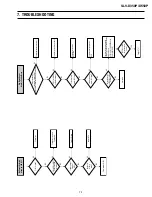
NO DVD LD ON
DIC1-124 is "H"?
Check LD of Pick-up.
Check DIC1
Yes
No
QLP2 Collector is "L"?
Check QLP2
Yes
No
MDQ1 Collector is "H"?
Check MDQ1
Yes
No
(DVD Section)
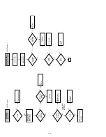
Abnormal rotation of
disc motor
SPDRV output is normal?
(DIC1-76)
DIC1-140(SPDL-SENS)
Input is normal?
Check disc motor.
Check DRIC1 soldering.
Resoldering DIC1.
Yes
Yes
No
No
Input of A, B, C, D
signal is normal?
(DIC1-114~117)
Check DIC1 perpheral circuit
and DCON3 connector
Yes
No
(DVD Section)
Summary of Contents for RMT-V501C
Page 10: ... 10 MEMO ...
Page 67: ...3 BLOCK DIAGRAM 3 2 3 1 SLV D350P D550P ...
Page 68: ...3 4E MEMO ...
Page 70: ...4 3 4 4 4 1 VCR MAIN FUNCTION TIMER COMPONENT SIDE ...
Page 71: ...4 6 4 5 CONDUCTOR SIDE ...
Page 72: ...4 7 4 8 COMPONENT SIDE CONDUCTOR SIDE 4 2 DVD MAIN ...
Page 73: ...4 10 4 9 4 3 DIAL TIMER SLV D550P Only COMPONENT SIDE CONDUCTOR SIDE ...
Page 74: ...4 12E MEMO ...
Page 76: ... BLOCK IDENTIFICATION OF MAIN PCB 5 3 5 4 Component Side Conductor Side VCR MAIN PCB ...
Page 77: ...5 1 S M P S 5 6 5 5 ...
Page 78: ...5 2 POWER DRIVE 5 7 5 8 ...
Page 79: ...5 3 LOGIC FUNCTION TIMER 5 10 5 9 ...
Page 80: ...5 4 A V 5 11 5 12 ...
Page 81: ...5 5 Hi Fi MTS 5 14 5 13 ...
Page 82: ...5 6 INPUT OUTPUT 5 15 5 16 ...
Page 83: ...5 7 DVD 5 18 5 17 ...
Page 84: ...MEMO 5 20E ...
Page 112: ...7 18E MEMO ...