


2-8
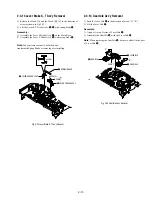
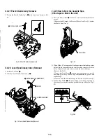
2-4-4 Slider FL Drive, Gear FL Cam Removal
1) Pull the Slider FL Drive
1
to the front direction.
2) Remove the Slider FL Drive
1
in the direction of arrow. (Refer to
Fig. 2-14)
3) Remove the Gear FL cam
2
.
Note:
When reinstalling be sure to reassemble Slider FL drive
1
after you insert the Boss of Lever FL ARM-R in Groove of Slider FL
drive
1
.
Assembly:
Align the Gear FL Cam
1
with the Gear worm wheel
Post as shown drawing.
(Refer to Timing point)
Fig. 2-14 Slider FL Drive Removal
Fig. 2-15 Gear FL Cam, Gear Worm
1
GEAR FL CAM
GEAR WORM WHEEL
POST
TIMING POINT
2-4-3 Lever FL Door Removal
1) Release the Hook
2
and Remove the Lever FL Door
1
in the
direction of arrow “A”.
Fig. 2-13 Lever FL Door Removal
"B"
"C"
"A"
2
LEVER FL DOOR
1
SLIDER FL DRIVE
1
SLIDER FL DRIVE
2
GEAR FL CAM
Summary of Contents for RMT-V501C
Page 10: ... 10 MEMO ...
Page 67: ...3 BLOCK DIAGRAM 3 2 3 1 SLV D350P D550P ...
Page 68: ...3 4E MEMO ...
Page 70: ...4 3 4 4 4 1 VCR MAIN FUNCTION TIMER COMPONENT SIDE ...
Page 71: ...4 6 4 5 CONDUCTOR SIDE ...
Page 72: ...4 7 4 8 COMPONENT SIDE CONDUCTOR SIDE 4 2 DVD MAIN ...
Page 73: ...4 10 4 9 4 3 DIAL TIMER SLV D550P Only COMPONENT SIDE CONDUCTOR SIDE ...
Page 74: ...4 12E MEMO ...
Page 76: ... BLOCK IDENTIFICATION OF MAIN PCB 5 3 5 4 Component Side Conductor Side VCR MAIN PCB ...
Page 77: ...5 1 S M P S 5 6 5 5 ...
Page 78: ...5 2 POWER DRIVE 5 7 5 8 ...
Page 79: ...5 3 LOGIC FUNCTION TIMER 5 10 5 9 ...
Page 80: ...5 4 A V 5 11 5 12 ...
Page 81: ...5 5 Hi Fi MTS 5 14 5 13 ...
Page 82: ...5 6 INPUT OUTPUT 5 15 5 16 ...
Page 83: ...5 7 DVD 5 18 5 17 ...
Page 84: ...MEMO 5 20E ...
Page 112: ...7 18E MEMO ...