


1-9 (E)
PMW-EX1R
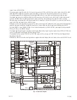
Main functions of the system controller and peripherals
(1) Reading operation switch information
Reading the switch information and the LED control are performed by I
2
C bus communication with each
sub-microprocessor.
.
Handle switch: IC100 on the KSW-55 board
.
Inside panel switch: IC200 on the SWC-50 board
.
Rear panel switch: IC301 on the ASW-68 board
.
Power supply switch: IC1001 on the RE-273 board
(2) Watch IC (RTC) control
The watch IC (IC100) is built onto the DAP-41 board.
The watch IC (IC100) is backed up by a lithium coin battery, and the current time is read or set via IC200
on the SWC-50 board.
(3) Infrared remote control demodulation
The RM-224 board has an IC (IC1) for infrared remote control signal demodulation, and it receives the
command codes via IC100 on the KSW-55 board.
(4) Info-Battery communication
The Info-Battery of SM bus speci
fi
cations is supported.
The serial terminal of the battery connector is connected to IC1001 on the RE-273 board. This IC1001
read the battery authentication, battery type, remaining power, and other information and send them to the
system controller via I
2
C bus communication.
(5) Power supply voltage detection
The power supply voltage at the DC IN connector is measured by the A/D port on IC1001 on the RE-273
board, and it is posted to the system controller as the input voltage value.
(6) Power system control
IC1001 on the RE-273 board checks that the power switch on the PMW-EX1R is turned ON, and turns on
the system controller of IC2900. After that, it controls the power for each circuit block according to the
system controller.
The system controller controls the respective power supply systems in the RE-272 and RE-273 boards
according to the operation mode of the device, via the power supply
μ
-processor (IC1001) on the RE-273
board.
By turning off the power systems to unnecessary circuits blocks, power can be saved.
7. EVF/SDI
System
SDI block
TX-131 Board
This board receives the parallel video signal with FPGA (IC200) and outputs the SDI signal.
Furthermore, it performs audio or timecode embedding.
The video and audio signals are supplied from CN700 on the DPR-311 board to CN100 on the TX-131
board with B to B connector.
Output SDI signals are supplied to CN500 through the cable driver (IC500).
Output SDI signals are then supplied from CN500 to the coaxial connector via the mini coaxial connector
and mini coaxial cable.
The PLL circuit is used to reduce jitter of the HD-SDI clock signal.
The FPGA (IC200) is controlled by IC600 on the DPR-311 board through 4-line serial communication.