1-6.
Circuit Protection Parts
1-6-1.
Circuit Protection Element
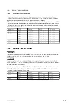
This unit is equipped with positive-characteristic thermistors (power thermistors) as circuit protection elements.
The positive-characteristic thermistor limits the electric current flowing through the circuit as the internal resistance
increases when an excessive current flows or when the ambient temperature increases.
If the positive-characteristic thermistor works, turn off the main power of the unit and inspect the internal circuit of the
unit. After the cause of the fault is eliminated and the positive-characteristic thermistor is cooled down, turn on the main
power again. The unit works normally. It takes about one minute to cool down the positive-characteristic thermistor
after the main power is turned off.
Board name
Ref. No.
Address
Part No.
Hold current
DCP-56
THP100
A1 (Side B)
1-771-845-21
200 mA/25
℃
DPR-343
THP130
A2 (Side A)
1-805-726-11
200 mA/25
℃
THP131
A2 (Side A)
1-805-726-11
200 mA/25
℃
THP132
A3 (Side A)
1-805-726-11
200 mA/25
℃
THP133
A3 (Side A)
1-805-726-11
200 mA/25
℃
RE-298
THP100
B2 (Side B)
1-803-615-21
500 mA/25
℃
RE-300
THP100
A1 (Side B)
1-803-615-21
500 mA/25
℃
1-6-2.
Replacing Fuses and IC Links
WARNING
Fuses and IC links are essential parts for safe operation. Be sure to use the parts specified in this manual.
Replacing any fuse or IC link with an unspecified one may cause fire or electric shock.
CAUTION
Replacing any fuse or IC link is replaced while power is supplied to the unit may cause electric shock.
Before replacing any fuse or IC link, turn off the POWER switch and also disconnect the battery pack and
the cable from the DC IN connector.
This unit is equipped with fuses and IC links. The fuses and IC links blow if overcurrent flows in the unit due to an
abnormality, In that case, turn off the power of the unit, inspect inside of the unit, and then remove the cause of the
overcurrent. After that, replace the defective parts.
Board name
Ref.No.
Address
Part No.
Rating
IF-1188
PS100
A1 (Side A)
1-576-122-21
0.4 A/72 V
PS101
A1 (Side A)
1-576-122-21
0.4 A/72 V
RE-299
F100
A2 (Side B)
1-576-329-21
10A/125V
PMW-200/PMW-EX280
1-14
Summary of Contents for PMW-200
Page 1: ...SOLID STATE MEMORY CAMCORDER PMW 200 PMW EX280 SERVICE MANUAL 1st Edition Revised 1 ...
Page 4: ......
Page 8: ......
Page 10: ......
Page 30: ......
Page 38: ...3 Install the removed parts by reversing steps of removal PMW 200 PMW EX280 2 8 ...
Page 82: ......
Page 96: ......
Page 128: ......
Page 130: ......
Page 132: ......
Page 133: ......


