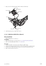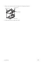
10. Remove the main heat spreader DCP. (Refer to
11. Remove the handle assembly. (Refer to
12. Remove the front lens assembly. (Refer to
.)
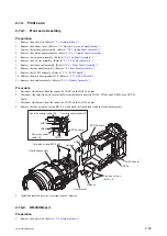
Procedure
1.
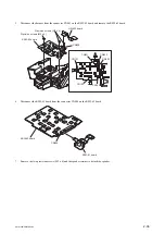
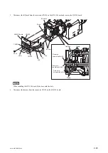
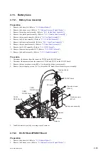
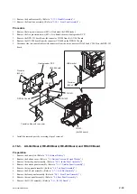
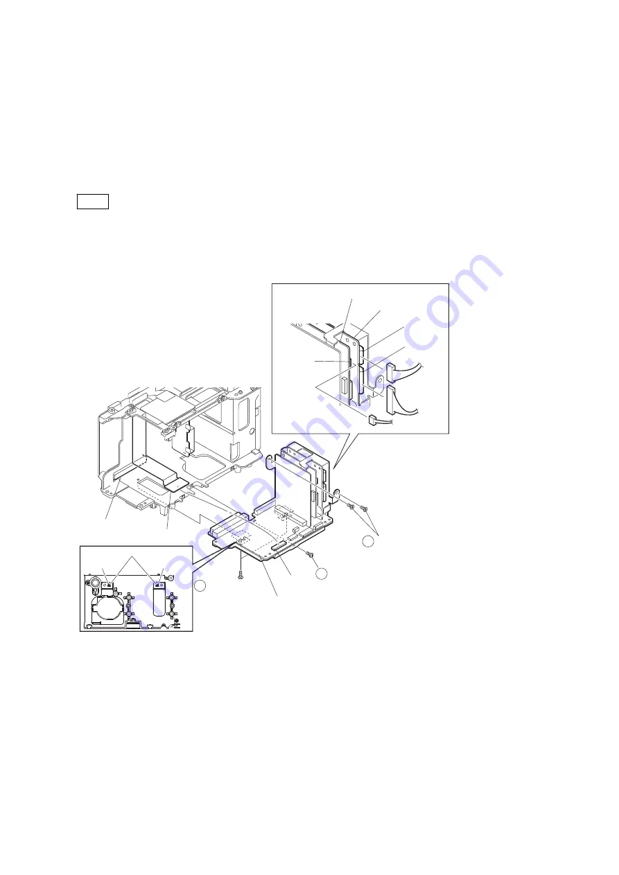
Disconnect the harness from the connector CN202 on the RE-298 board.
2.
Disconnect the harnesses from the connectors CN100 and CN101 on the RE-299 board.
3.
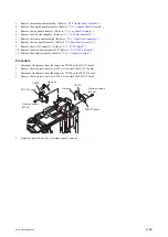
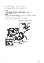
Remove the five precision screws (M2 x 4).
Note
When installing these precision screws, push the U groove of the bracket AU against the positioning pin, and tighten
the screws in the order of numbers shown in the figure.
4.
Disconnect the HN-386 board from the connector CN104 on the AU-342 board.
5.
Disconnect the AU-342 board from the connector CN2400 on the DPR-343 board.
Positioning pins
U groove
U groove
1
2
3 Precision screws
(M2 x 4)
Precision screw
(M2 x 4)
Precision screws
(M2 x 4)
CN104
CN100
CN202
CN101
AU-342board
HN-386 board
CN2400
(DPR-343 board)
RE-299 board
RE-298 board
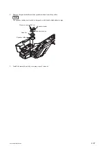
6.
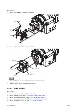
Remove the precision screws (M2 x 4).
PMW-200/PMW-EX280
2-49
Summary of Contents for PMW-200
Page 1: ...SOLID STATE MEMORY CAMCORDER PMW 200 PMW EX280 SERVICE MANUAL 1st Edition Revised 1 ...
Page 4: ......
Page 8: ......
Page 10: ......
Page 30: ......
Page 38: ...3 Install the removed parts by reversing steps of removal PMW 200 PMW EX280 2 8 ...
Page 82: ......
Page 96: ......
Page 128: ......
Page 130: ......
Page 132: ......
Page 133: ......

