background image

8-12

FWD-50PX1

8-12

B

B

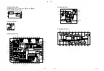
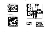
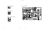
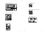
B (4/8) TC74VHC541FT (IC1010)
B (4/8) TC74VHCT541AFT (IC1011)

1

2

3

4

5

6

7

16

17

18

19

20

15

14

13

12

11

8

9

10

A1

G1

A2

A3

A4

GND

A6

A7

A8

A5

VDD

G2

Y3

Y1

Y2

Y5

Y4

Y6

Y7

Y8

B (4/8) TC74VHCT14AFT (IC1012)

GND

V

DD

1

2

3

4

5

6

7

14

13

12

11

10

9

8

B (7/8) SN74LV4053APWR (IC405)

1

2

3

4

5

6

7

8

11

10

9

16

15

14

12

X1

X0

Y1

YC

Y0

EN

V

EE

GND

V

DD

XC

ZC

Z0

13 Z1

AZ

AX

AY

OPEN

OPEN

OPEN

B (3/8), (6/8) TC4W53FU (IC208, IC209, IC3)

8

7

6

5

1

2

3

4

VCC

CH1

CH0

ADR

COM

INH

VEE

VSS

B (8/8) SN74LV123APWR (IC604)

16

1

15

14

13

12

VCC

1 REXT/CEXT

CEXT 1

1 Q

2Q

2 CLR

2B

2A

1A

1B

1 CLR

1Q

2Q

CEXT 2

2 REXT/CEXT

GND

11

10

9

2

3

4

5

6

7

8

CLR

Q

Q

CLR

Q

Q

B (3/8) SI-3025LSA (IC201, IC202)

IN (MIC)

VC

+

_

TSD

VOUT

IN (PTR)

GND

3

7,8

5,6

1

4

B (4/8) SN74CBTD3306 (IC1019)

10E

1

8

VCC

1A

2

1B

3

GND

4

6

2B

5

2A

7

2OE

V

DD

2

V

SS

CD

4

5

OUT

1

V

REF

DELAY

B (4/8) S-80828CNNB-B8NT2G (IC1005)
B (4/8) S-80842CNNB-B83T2G (IC1020)

B (4/8) RS5C348A (IC1003)

32kHz

OUTPUT

CONTROL

OSC

DIVIDER

CORRECTION

DIV

OSC

DETECT

COMPARATOR_W

COMPARATOR_D

ALARM_W REGISTER

(WEEK, MIN, HOUR)

ALARM_W REGISTER

(MIN, HOUR)

VOLTAGE

DETECT

TIME COUNTER

(SEC, MIN, HOUR, WEEK, DAY, MONTH, YEAR)

I/O

CONTROL

ADDRESS

REGISTER

SHIFT REGISTER

ADDRESS

DECODER

INTERRUPT CONTROL

1

9

8

6

7

3

4

2

5

10 V

DD

V

SS

SCLK

SI

SO

CE

/INTR

OSCOUT

OSCIN

32KOUT

Summary of Contents for FWD-50PX1 (English: pgs. 52-97)

Page 1: ...FLAT WIDE DISPLAY FWD 50PX1 FWD 50PX1N SERVICE MANUAL 1st Edition FLAT PANEL DISPLAY SPEAKER SYSTEM SS SP50FW TV STAND SU 50FW ...

Page 2: ...u befolgen Andere als die angegeben Wartungsarbeiten dürfen nur von Personen ausgeführt werden die eine spezielle Befähigung dazu besitzen AVERTISSEMENT Ce manual est destiné uniquement aux personnes compétentes en charge de l entretien Afin de réduire les risques de décharge électrique d incendie ou de blessure n effectuer que les réparations indiquées dans le mode d emploi à moins d être qualifi...

Page 3: ... og type Levér det brugte batteri tilbage til leverandøren ADVARSEL Lithiumbatteri Eksplosjonsfare Ved utskifting benyttes kun batteri som anbefalt av apparatfabrikanten Brukt batteri returneres apparatleverandøren VARNING Explosionsfara vid felaktigt batteribyte Använd samma batterityp eller en likvärdig typ som rekommenderas av apparattillverkaren Kassera använt batteri enligt gällande föreskrif...

Page 4: ...r oder nach längerer Gebrauchsdauer der Batterien nicht mehr einwandfrei funktioniert Um sicherzugehen kleben Sie die Batteriepole z B mit einem Klebestreifen ab oder geben Sie die Batterien einzeln in einen Plastikbeutel For the customers in the U S A and Canada RECYCLING LITHIUM ION BATTERIES Lithium Ion batteries are recyclable You can help preserve our environment by returning your used rechar...

Page 5: ...1 5 Service Position 1 12 1 5 1 Service Position of the B and Q Boards 1 12 1 6 Packaging of the Plasma Display Panel When It Is Shipped to Pioneer Corporation 1 13 1 7 Backup Battery Replacement 1 14 1 8 Unleaded Solder 1 14 1 9 Warning on Power Connection 1 14 2 Electrical Adjustments 2 1 Equipment Required 2 1 2 2 Electrical Adjustments Using the Service Mode 2 1 2 3 White Balance Adjustment 2 ...

Page 6: ...6 1 6 2 Exploded Views 6 2 6 3 Electrical Parts List 6 8 6 4 Packing Materials Supplied Accessories 6 24 6 5 SS SP50FW 6 24 7 Block Diagrams B 1 3 Q 1 2 SP 7 1 B 2 3 7 2 B 3 3 Q 2 2 H1 H2 S 7 3 8 Schematic Diagrams B 8 2 H1 H2 SP 8 14 Q 8 15 S 8 20 U1 FWD 50PX1 8 21 Frame Wiring 8 22 9 Board Layouts B 9 2 Q 9 4 H1 9 6 H2 9 6 S 9 6 SP 9 6 U1 FWD 50PX1 9 7 ...

Page 7: ...0PX1 Section 1 Service Overview S boards H2 board Y drive board Q board U1 board FWD 50PX1 H1 board B board SP board Interface board Digital video board X drive board S board Power unit board 1 1 Board Location ...

Page 8: ...et and replacing the board place the unit on the conductive cushion 1 2 1 Rear Cover Assembly 1 Loosen the two panel securing screws then remove the U1 block assembly FWD 50PX1 only 2 Remove the four screws PSW M6 x 20 then remove the four nylon washers and four knobs 3 Remove the fourteen screws PSW3 x 20 and eight screws PSW3 x 8 then remove the rear cover assembly while holding the handle 4 Att...

Page 9: ...ductive cushion 1 Remove the rear cover assembly Refer to Section 1 2 1 2 Remove the two screws BVTP3 x 8 then remove the control button panel 3 Disconnect the harness from the connector on the H2 board 4 Remove the three screws BVTP3 x 8 then remove the control button and H2 board 5 Remove the screw BVTP3 x 8 then remove the light tube and H1 board 6 Disconnect the harness from the connector on t...

Page 10: ...he two UL tapes then disconnect the seven harnesses and the flexible flat cable connected to the Q board 6 Remove the six screws then remove the Q board and partition Q PSW 3 x 6 PSW 3 x 6 PSW 3 x 6 PSW 3 x 8 black M8 x 16 CN3007 CN3005CN3008 CN3012 CN3011 CN3001 CN3006 CN3002 Q board Conductive cushion Q board Hexagonal screw Q terminal plate Harnesses Partition Q UL tapes Copper foil tape Q B sh...

Page 11: ...ove the Q B shield cover Refer to step 2 of Section 1 3 1 3 Remove the two UL tapes then disconnect the eight harnesses and the flexible flat cable connected to the B board 4 Remove the six screws then remove the B board 5 Remove the lithium battery from the battery holder on the B board 6 Install the B board in the reverse order of steps 1 to 5 n Place and fix the harnesses to connect the Q board...

Page 12: ...e order of steps 1 to 3 PSW 3 x 6 PSW 3 x 6 PSW 3 x 6 Harness Harness Harness S board S board S board Conductive cushion 1 3 4 S Board n The three S boards are installed in this unit When replacing them remove install in the same procedure 1 Remove the rear cover assembly Refer to Section 1 2 1 2 Disconnect the harness from the S board 3 Remove the screw then remove the S board 4 Install the S boa...

Page 13: ...s 3 Remove the harness from the eight clampers 4 Remove the bolt M8 x 16 and four screws PSW3 x 6 then remove the QB block assembly in the direction shown by the arrow 5 Remove the three screws PSW3 x 6 then remove the side frame and board cover assembly 6 Remove the four screws then remove the option case bracket assembly 7 Disconnect the harness and flexible flat cable from the connectors on the...

Page 14: ...ables Digital video board Harnesses Harness Board holders Board holders Board holders Interface board Harnesses 1 3 7 Digital Video Board Interface Board 1 Remove the rear cover assembly Refer to Section 1 2 1 2 Remove the QB block assembly 3 Remove the power unit Refer to steps 2 and 3 of Section 1 4 1 4 Disconnect all harnesses and flexible flat cables from the connectors on the digital board 5 ...

Page 15: ... the nine harnesses from the connectors on the power unit 3 Remove the bolt M8 x 16 and four screws PSW3 x 6 then remove the QB block assembly 4 Remove the four connectors A 5 Remove the three connectors B 6 Disconnect the three harnesses from the connectors on the interface board 7 Disconnect the harness from the connector on the SP board 8 Remove the harness from the four purse locks 9 Remove th...

Page 16: ... DC Fan For Q B Mount n When attaching the DC fan make sure that the orientation of imprinting is correct 1 Remove the rear cover assembly Refer to Section 1 2 1 2 Remove the connector and two screws then remove the DC fan 3 Attach the DC fan in the reverse order of steps 1 and 2 ...

Page 17: ...tion 1 4 1 4 Remove the S board Refer to Section 1 3 4 5 Remove the Y drive board Refer to Section 1 3 5 6 Remove the X drive board Refer to Section 1 3 6 7 Remove the digital video board and interface board Refer to Section 1 3 7 8 Remove the power unit Refer to 1 4 1 9 Remove the cushions 15x25 attached to the heads of the three bolts on the right side as viewed from backside 10 Remove the five ...

Page 18: ...ver assembly Refer to Section 1 2 1 2 Remove the two cushions 15x25 attached to the two screws 3 Remove the bolt M8 x 16 and two screws then remove the QB shield assembly 4 Attach the four knobs to the unit by the four screws 5 Attach the four knobs to the holes of the each stand Unit Unit Stands Stands Bolt M8 x 16 PSW M6 x 20 PSW M6 x 20 PSW 3 x 6 Q board Knobs Knobs Q B shield cover B board Uni...

Page 19: ...a Display Panel When It Is Shipped to Pioneer Corporation PP bands Carton Upper Pad R Upper Pad L Upper Pad L Under Pad R Under Carton Under POSITIONING SCREWS Individual inner case FRONT LID SERVICE MODULE Individual inner case Screws 12 pcs ...

Page 20: ...he unleaded solder for the printed circuit board printed with the lead free mark The unleaded solder melts at a temperature about 40 dC higher than the ordinary solder therefore it is recom mended to use the soldering iron having a temperature regulator The ordinary soldering iron can be used but the iron tip has to be applied to the solder joint for a slightly longer time The printed pattern copp...

Page 21: ...o exit the Service Mode Operation of remote commander in the Service Mode The six keys of MENU ENTER and are the basic operation keys in the same manner as in the user adjustment The other keys can be operated in the same manner as in the user adjustment The electrical adjustments using the Service Mode become necessary in the following cases When one of the following adjustments is made adjustmen...

Page 22: ...ory User Memory Factory c White Balance It initializes Color Temp 1 and Color Temp 2 of the COMMON DATA AREA shown in Table 1 It initializes the color temperature High Mid and Low and all data of user setup 1 to 3 to 00 It also initializes the user name to User1 User2 and User3 d Prog Gamma This command is not used in this machine e Prog Preset It initializes the PRESET DATA AREA page 2 13 shown i...

Page 23: ...stment of PAL and SECAM signals are performed in c Sub Color upon completion of the NTSC signal adjustment Adjustment range is from 0 to 63 Service Mode Chroma Decoder Hue Sub Contrast 8 Sub Color Sharp Gain 8 Sharp f0 3 Y Out Level 18 C Out Level 10 Y Delay Cb Offset 8 Cr Offset 8 By Adj SECAM 8 Ry Adj SECAM 8 h Y Delay Y delay for the respective signals can be adjusted by YDL NTSC YDL PAL YDL SE...

Page 24: ...Cont Video and Sub Brt Video and from 0 to 63 for Cb Offset Video and Cr Offset Video AD Calibration Adjustment Refer to Section 2 4 AD Calibration Adjustment Service Mode AD Converter Cal Mode off RGB Calibration YUV Calibration Video Calibration 4 White Balance Menu structure White balance of PDP panel is adjusted a Window This machine has the built in window signal for white balanced adjustment...

Page 25: ...s from 32 76180 to 32 77420 kHz f Serial Number It sets serial number g Fan Status Menu structure Fan Control You can set the 8 0 to 12 0 V to the fan drive voltage using Ref Voltage Use this command for checking operation of the fan drive circuit Factory default setting 8 0 V Ref Voltage You can set the any desired voltage to the fan drive voltage Range of setting is from 8 0 V to 12 0 V the sett...

Page 26: ...iting RAM Then modify the data on the editing RAM and save the editing contents to the specified preset area of EEPROM In addition to the default preset data that has been set already when shipped from the factory you can edit the various data from the already saved data in EEPROM or the signal data that is being input at this moment The following example shows the case the data stored in the EEPR...

Page 27: ...eflected on screen If you press the ENTER key again the screen returns to the previous menu Among the adjustment items the three types of adjustment H Freq V Freq and Sync Pol cannot be modified 2 Table When you select the data stored in the preset area move the cursor to this item and press ENTER Select the desired data using the key The selected data is copied to the editing RAM This mode is pre...

Page 28: ...y b Data Edit Menu structure You can edit the data contents of the editing RAM 1 H Freq It sets the horizontal frequency n When Current Data Select is selected in the Original Data Select this item cannot be modified because the presently entered signal is selected for editing 2 V Freq It sets the vertical frequency n When Current Data Select is selected in the Original Data Select this item canno...

Page 29: ... pulse width Wcp is given by the equation below Wcp Clamp Width Horizontal sync frequency x H Total Pixel seconds 0 0 0 0 0 0 0 0 1 ON 1 2 3 4 0 OFF Upper 4 bits are not used 14 Format Flag It sets ON OFF of the following respective items in units of bit 1 Setting the IP converter Set to OFF during normal operation 2 Setting interlace It sets the interlace input ON When the input signal is the int...

Page 30: ...ta exists within a preset area the specification that has the smaller preset number has priority Service Mode Preset Edit Save Area Select Save Are 1 1 Selects the preset data area Data Save that stores the data 2 Executes saving of the data Service Mode Service Status Signal Sync Power Supply Fan Temp Status Warning Status Operation Time H Software Version PLD Version Service Mode Service Status ...

Page 31: ...Temp 44 dC NO ACK DEV 0004 b Power Supply Menu structure Main DC voltages of the machine are displayed Digital 5 V Internal 5 V power supply voltage is dis played Digital 3 V Internal 3 3 V power supply voltage is displayed Analog 6 V Internal 6 V power supply voltage is dis played c Fan Temp Status Menu structure The internal temperature of the machine and the fan operating status are displayed F...

Page 32: ...on error DEC Init Chroma decoder initialization error DC Init Power voltage digital system 5 V digital system 3 3 V analog system 6 V error Power Off Power off sequence error e Operation Time Accumulative operating hours are indicated In units of hour f Software Version Software version is indicated g PLD Version PLD version is indicated Service Mode Service Status Warning Status EEP ID OK EEP Sav...

Page 33: ...440 to 0x045F Reserved 0x0460 to 0x047F Reserved 0x0480 to 0x049F Reserved 0x04A0 to 0x04BF Reserved 0x04C0 to 0x04DF Reserved 0x04E0 to 0x04FF Reserved 0x0500 to 0x051F Reserved 0x0520 to 0x053F Reserved 0x0540 to 0x055F Reserved 0x0560 to 0x057F Reserved 0x0580 to 0x059F Reserved 0x05A0 to 0x05BF Reserved 0x05C0 to 0x05DF Reserved 0x05E0 to 0x05FF Name Address LAST Area 1 0x0600 to 0x061F MEMORY...

Page 34: ...x0FC0 to 0x0FDF 0x0FE0 to 0x0FFF Area 21 0x1000 to 0x101F 0x1020 to 0x103F 0x1040 to 0x105F 0x1060 to 0x107F Name Address LAST Area 22 0x1080 to 0x109F MEMORY 0x10A0 to 0x10BF AREA 0x10C0 to 0x10DF 0x10E0 to 0x10FF Area 23 0x1100 to 0x111F 0x1120 to 0x113F 0x1140 to 0x115F 0x1160 to 0x117F Area 24 0x1180 to 0x119F 0x11A0 to 0x11BF 0x11C0 to 0x11DF 0x11E0 to 0x11FF Area 25 0x1200 to 0x121F 0x1220 t...

Page 35: ...BF 0x1FC0 to 0x1FDF 0x1FE0 to 0x1FFF Name Address Reserved Area 1 0x1600 to 0x161F 0x1620 to 0x163F 0x1640 to 0x165F 0x1660 to 0x167F Area 2 0x1680 to 0x169F 0x16A0 to 0x16BF 0x16C0 to 0x16DF 0x16E0 to 0x16FF Area 3 0x1700 to 0x171F 0x1720 to 0x173F 0x1740 to 0x175F 0x1760 to 0x177F Area 4 0x1780 to 0x179F 0x17A0 to 0x17BF 0x17C0 to 0x17DF 0x17E0 to 0x17FF Area 5 0x1800 to 0x181F 0x1820 to 0x183F ...

Page 36: ...16inch 832 x 624 RGB Progressive 57 285 49 724 1152 320 32 64 224 832 22 SPECIAL 1024x576 60Hz 1024 x 576 RGB Progressive 48 375 36 427 1328 304 48 128 128 1024 23 VESA 1024x768 60Hz 1024 x 768 RGB Progressive 65 000 48 363 1344 320 24 136 160 1024 24 VESA 1024x768 70Hz RGB Progressive 75 000 56 476 1328 304 24 136 144 1024 25 VESA 1024x768 75Hz RGB Progressive 78 750 60 023 1312 288 16 96 176 102...

Page 37: ... OFF STANDARD 293M NORMAL 60 000 517 37 480 8 6 23 NO YES P P 66 8 OFF ON OFF OFF STANDARD 293M FULL 74 550 667 43 624 3 3 37 NO YES N N 27 8 OFF ON OFF OFF STANDARD 293M NORMAL 60 210 605 29 576 3 1 25 YES NO 47 8 OFF ON OFF OFF STANDARD 293M NORMAL 60 004 806 38 768 6 3 29 NO YES N N 36 8 OFF ON OFF OFF STANDARD 293M NORMAL 70 069 806 38 768 6 3 29 NO YES N N 29 8 OFF ON OFF OFF STANDARD 293M NO...

Page 38: ... 625 1000 250 113 32 105 750 COMPOSITE 56 SDTV SECAM_ YUV Interlace 28 125 15 625 1000 250 113 32 105 750 COMPOSITE 57 SDTV 443NT_ 720 x 483 YUV Interlace 28 322 15 734 968 218 132 32 54 750 COMPOSITE 58 SDTV PAL M_ 720 x 575 YUV Interlace 28 125 15 734 968 218 132 32 54 750 COMPOSITE 59 SDTV PAL N_ YUV Interlace 28 125 15 625 1000 250 113 32 105 750 COMPOSITE 60 SDTV BW_ 720 x 483 YUV Interlace 2...

Page 39: ... 58 ON OFF ON ON STANDARD 293M NORMAL 50 000 625 91 27 2 62 534 SOG NO 30 58 ON OFF ON ON STANDARD 293M NORMAL 60 000 525 71 24 2 45 454 SOG NO 30 58 ON OFF ON ON STANDARD 293M NORMAL 60 000 525 71 24 2 45 454 SOG NO 30 58 ON OFF ON ON STANDARD 293M NORMAL 50 000 625 91 27 2 62 534 SOG NO 30 58 ON OFF ON ON STANDARD 293M NORMAL 60 000 525 71 24 2 45 454 SOG NO 30 58 ON OFF ON ON STANDARD 293M NORM...

Page 40: ...90 IRE to INPUT1 2 Adjust the Sub Cont RGB of the RGB Calibration until the G detection value becames the setup value Setup value 220 3 3 Adjust the Red Gain and Blue Gain until the R and B detection values become the G detection value 4 Set the RGB signal to the VGA 640 x 480 60 all gray 20 IRE 5 Adjust Red Bias Green Bias and Blue Bias until the R B and G detection values become the setup value ...

Page 41: ...htness as D Select Hue of Chroma Decoder and adjust Hue NTSC until 2 has the same brightness as B and 3 has the same brightness as C Repeat the above described adjustments until all the adjustment values are satisfied at the same time Tracking 5 Input the PAL SMPTE color bar signal to Video Input 6 While observing the screen display adjust the PAL Sub Color as follows Select Service Mode Chroma De...

Page 42: ... menu and set it to On 2 Connect a frequency counter as shown below and measure the frequency 3 Select Watch Error in General of the Service Mode menu and enter the measurement result 4 Set 32k Clock Out to Off 1 2 3 CN1003 VCC CLOCK GND 10kΩ Frequency counter Make the cable as short as possible ...

Page 43: ...V Picture does not appear Check the indication on the indicator in the lower right of the front panel STAND BY 2 times 3 times 4 times 5 times 6 times When error code is detected from the panel When temperature increase of the power supply block or temperature increase inside the unit due to the sensor board is detected When a fan stop or failure of the fan drive circuit is detected When 3 3 V dig...

Page 44: ...indicator flashes at the interval of 0 4 seconds continuously At the same time the corresponding item shows the NG indication in the service menu The NG indication is not reset and is accumulated unless the AC cord is disconnected If the abnormal condition exceeds the allowable limit it forcibly activates the shutdown operation and picture will not be displayed any more At this time the Standby in...

Page 45: ...n is activated 4 Detecting the communication error with each device 1 NO ACK DEV It indicates if the communication with the respective devices controlled by the I2 C bus is correctly established or not Bit 0 Audio Processor Each bit 0 OK 1 NG Bit 1 Audio Switch Bit 2 AV Switch Bit 3 Closed Caption Decoder Bit 4 3D Combfilter Bit 5 Chroma Decoder Bit 6 PDP No Use for PFM 50C1 E Bit 7 Tuner No Use f...

Page 46: ...K RTC Init OK 1 RTC VDET OK 2 RTC XSTOP OK 3 PDP Init OK DEC Init OK DC Init OK Power Off OK 7 Detecting chroma decoder initialization error 1 DEC Init In the case of the chroma decoder unit initialization error NG is displayed 8 Detecting abnormal voltage of the internal power supply and shutting power supply down 1 DC Init When the internal power supply digital system 5 V digital system 3 3 V or...

Page 47: ... off sequence is not per formed correctly NG is displayed Failure of the power supply block or the PDP is suspected Service Mode Service Status Warning Status EEP ID OK EEP Save OK EEP Load OK RTC Init OK RTC VDET OK RTC XSTOP OK PDP Init OK DEC Init OK DC Init OK Power Off OK 1 ...

Page 48: ......

Page 49: ... switched by VIDEO SW IC3004 The selection of with without LPF for the switched signals is performed by VIDEO SW IC3006 then the signals are output to the B board from CN3001 The H V SYNC signal at the time of RGB signal input is input to Selector IC3005 In the same way the selected SYNC signal is output from CN3001 These SW controls are performed by the port control from the microcomputer The sou...

Page 50: ... by 3Line Comb Filter IC205 Each output is selected by Selector IC208 IC209 and then returned to Color Decoder IC2 decoded to YUV signal and output to AD converter IC403 In the case that it is compliant with Closed Caption the RGB signal from Closed Caption Decoder IC4 is added and output The AD converter IC403 has the two input channels and it is provided with a built in broad band video switch T...

Page 51: ...in QFP HD64F2633TE 1 TOP VIEW 120pin QFP IP00C713 1 TOP VIEW 256pin QFP L88M05T FA TL 1 3 LM35DZ 1 2 3 M52347FP TE TC74VHC541FT EL TC74VHCT541AFT EL 1 TOP VIEW 20pin SOP M52758FP 1 TOP VIEW 36pin SOP MAX202CSE MAX202CSE T MC74HC4052F SN74LV4053APWR TC74HC123AF TC74HC123AF EL TC74HC4052AF EL 1 TOP VIEW 16pin SOP MC141627FT 1 TOP VIEW 48pin QFP MM74HC32MTCX SN74HC32APWR SN74LV123APWR TC74HC125AF TC7...

Page 52: ...EE DTA144EE TL DTC144EE DTC144EE TL GND IN OUT DTC114EU DTC114EUA T106 GND IN OUT 1SS387 TPL3 DTZ10B MA2S111 K8 UDZSTE 1710B UDZS TE1712B UDZS TE17 33B UDZSTE 174 7B ANODE CATHODE 02CZ12 TE85L 1 2 3 1 2 3 1SS184 DAN202K DAN202K T 146 MA151WK TX 1 2 3 1 2 3 1SS362 TE85L 1SS226 MA157 TX 1 2 3 1 2 3 BRPG1211C 34 TR 1 2 4 3 3 1 4 2 DAP222 DAP222 TL MA3130WA TX 1 2 3 1 2 3 DTZ10B MA111 TX MA113 TX RD5 ...

Page 53: ...ts supplied by Sony differ from those used for the unit These are because of parts common ality and improvement Parts list has the present standardized repair parts 3 Stock of Parts Parts marked with o at SP Supply Code column of the spare parts list may not be stocked Therefore the delivery date will be delayed 4 Harness Harnesses with no part number are not registered as spare parts In need of r...

Page 54: ... Views PSW M6 x 20 PSW 3 x 8 PSW 3 x 8 PSW 3 x 6 PSW 3 x 6 PSW 3 x 6 PSW 3 x 6 PSW 3 x 6 PSW 3 x 8 PSW 3 x 8 PSW 3 x 8 FWD 50PX1 PSW 3 x 6 PSW 3 x 6 PSW 3 x 20 BVTP 3 x 8 WASHER 6 0 NYLON 1 2 3 4 5 7 7 8 9 10 11 12 13 13 14 14 15 16 6 17 18 ...

Page 55: ...10 1 o ASSY QB SHIELD COVER 9 1 469 778 11 o CLAMP FERRITE 10 1 756 157 11 s BATTERY LITHIUM CR1220 11 2 159 508 01 s CABLE COVER BOTTOM 12 2 159 533 01 s BOLT M8X16 13 3 680 613 11 o SUPPORT PC BOARD 14 4 035 160 01 s PURSE LOCK S DIA 12 15 4 081 315 02 s KNOB 16 4 083 966 01 s SCREW HEXAGON 17 4 090 178 01 o SHEET THERM B 1 18 4 090 179 01 o SHEET THERM B 2 7 623 927 01 s WASHER PLASTIC 6X0 5 7 ...

Page 56: ...BVTT 3 x 8 PSW 4 x 35 BVTP 3 x 8 BVTP 4 x 16 BVTP 4 x 16 BVTP 4 x 16 BVTP 3 x 8 BVTP 3 x 8 BVTP 3 x 8 BVTP 4 x 16 PSW 3 x 6 PSW 3 x 6 PSW 3 x 6 PSW 4 x 25 PSW 4 x 25 PSW 4 x 8 PSW 3 x 6 PSW 3 x 6 101 102 103 104 104 104 105 106 107 107 108 109 110 111 112 113 114 115 114 116 117 118 119 120 ...

Page 57: ...LAY PANEL PLASMA 110 1 816 887 12 s AC INLET WITH NOISE FILTER 111 2 159 493 02 s LIGHT GUIDE 112 2 159 494 01 s PANEL BUTTON CONTROL 113 2 159 495 01 s BUTTON CONTROL 114 2 159 533 01 s BOLT M8X16 115 2 990 241 02 s HOLDER A PLUG 116 3 225 496 01 o CLAMP FLAT CLAMP 45 117 9 885 061 43 s X DRIVE BOARD 118 9 885 061 44 s Y DRIVE BOARD 119 9 885 061 45 s DIGITAL VIDEO BOARD 120 9 885 061 46 s INTERF...

Page 58: ...art No SP Description 201 A 1080 534 A s SPEAKER 50R ASSY RP FOR SS SP50FW W PEARL WHITE A 1080 536 A s SPEAKER 50R ASSY RP FOR SS SP50FW S SILVER 202 A 1080 535 A s SPEAKER 50L ASSY RP FOR SS SP50FW W PEARL WHITE A 1080 537 A s SPEAKER 50L ASSY RP FOR SS SP50FW S SILVER 7 685 661 79 s SCREW BVTP4X12 EP FE ZNBK CM2 ...

Page 59: ...6 7 FWD 50PX1 Overall 301 302 SU 50FW No Part No SP Description 301 2 148 620 01 o REAR COVER 302 4 092 541 02 s FOOT ...

Page 60: ...56 1 126 394 11 s CAPACITOR ELECT 10MF 16V CHIP B BOARD Ref No or Q ty Part No SP Description C57 1 109 982 11 s CAPACITOR CHIP CERAMIC 1MF 10V C58 1 107 826 11 s CAPACITOR CHIP CERAMIC 0 1MF C59 1 162 970 11 s CAPACITOR CERAMIC 0 01MF 25V B C60 1 162 970 11 s CAPACITOR CERAMIC 0 01MF 25V B C61 1 107 826 11 s CAPACITOR CHIP CERAMIC 0 1MF C62 1 107 826 11 s CAPACITOR CHIP CERAMIC 0 1MF C63 1 126 39...

Page 61: ...IP CERAMIC 0 1MF C421 1 107 826 11 s CAPACITOR CHIP CERAMIC 0 1MF B BOARD Ref No or Q ty Part No SP Description C422 1 107 826 11 s CAPACITOR CHIP CERAMIC 0 1MF C423 1 107 826 11 s CAPACITOR CHIP CERAMIC 0 1MF C424 1 107 826 11 s CAPACITOR CHIP CERAMIC 0 1MF C425 1 107 826 11 s CAPACITOR CHIP CERAMIC 0 1MF C426 1 107 826 11 s CAPACITOR CHIP CERAMIC 0 1MF C427 1 107 826 11 s CAPACITOR CHIP CERAMIC ...

Page 62: ... 11 s CAPACITOR CHIP CERAMIC 0 1MF C846 1 107 826 11 s CAPACITOR CHIP CERAMIC 0 1MF B BOARD Ref No or Q ty Part No SP Description C847 1 107 826 11 s CAPACITOR CHIP CERAMIC 0 1MF C848 1 107 826 11 s CAPACITOR CHIP CERAMIC 0 1MF C849 1 107 826 11 s CAPACITOR CHIP CERAMIC 0 1MF C850 1 107 826 11 s CAPACITOR CHIP CERAMIC 0 1MF C851 1 126 391 11 s CAPACITOR ELECT 47MF 6 3V 105 C852 1 107 826 11 s CAPA...

Page 63: ...APACITOR CHIP CERAMIC 0 1MF C7239 1 107 826 11 s CAPACITOR CHIP CERAMIC 0 1MF C7240 1 107 826 11 s CAPACITOR CHIP CERAMIC 0 1MF C7241 1 107 826 11 s CAPACITOR CHIP CERAMIC 0 1MF C7244 1 126 392 11 s CAPACITOR CHIP ELECT100MF 6 3V C7245 1 126 392 11 s CAPACITOR CHIP ELECT100MF 6 3V C7246 1 126 392 11 s CAPACITOR CHIP ELECT100MF 6 3V C7247 1 126 392 11 s CAPACITOR CHIP ELECT100MF 6 3V C7248 1 126 39...

Page 64: ...UCTOR SMALL TYPE 1 00UH L601 1 412 058 11 s INDUCTOR SMALL TYPE 10UH B BOARD Ref No or Q ty Part No SP Description L602 1 412 030 11 s INDUCTOR CHIP 22UH 3225 L603 1 412 058 11 s INDUCTOR SMALL TYPE 10UH L604 1 412 030 11 s INDUCTOR CHIP 22UH 3225 L801 1 500 451 11 s MICRO INDUCTOR CHIP 41P750S L7001 1 781 667 12 s COIL COMMON MODE CHOKE L7002 1 781 667 12 s COIL COMMON MODE CHOKE L7003 1 781 667 ...

Page 65: ...scription R33 1 218 867 11 s RESISTOR CHIP 6 8K 1 10W 1608 R34 1 216 819 11 s RESISTOR CHIP 680 1 10W 1608 R35 1 216 821 11 s RESISTOR CHIP 1 0K 1 10W 1608 R36 1 216 821 11 s RESISTOR CHIP 1 0K 1 10W 1608 R37 1 216 821 11 s RESISTOR CHIP 1 0K 1 10W 1608 R38 1 216 817 11 s RESISTOR CHIP 470 1 10W 1608 R39 1 216 830 11 s RESISTOR CHIP 5 6K 1 10W 1608 R40 1 216 813 11 s RESISTOR CHIP 220 1 10W 1608 R...

Page 66: ... 822 11 s RESISTOR CHIP 1 2K 1 10W 1608 R255 1 218 853 11 s RESISTOR CHIP 1 8K 1 10W 1608 B BOARD Ref No or Q ty Part No SP Description R256 1 216 809 11 s RESISTOR CHIP 100 1 10W 1608 R257 1 216 839 11 s RESISTOR CHIP 33K 1 10W 1608 R258 1 216 836 11 s RESISTOR CHIP 18K 1 10W 1608 R260 1 216 813 11 s RESISTOR CHIP 220 1 10W 1608 R261 1 216 809 11 s RESISTOR CHIP 100 1 10W 1608 R262 1 216 821 11 s...

Page 67: ...626 1 216 833 11 s RESISTOR CHIP 10K 1 10W 1608 R627 1 216 833 11 s RESISTOR CHIP 10K 1 10W 1608 B BOARD Ref No or Q ty Part No SP Description R629 1 216 805 11 s RESISTOR CHIP 47 1 10W 1608 R630 1 216 805 11 s RESISTOR CHIP 47 1 10W 1608 R631 1 216 833 11 s RESISTOR CHIP 10K 1 10W 1608 R632 1 216 833 11 s RESISTOR CHIP 10K 1 10W 1608 R633 1 216 833 11 s RESISTOR CHIP 10K 1 10W 1608 R634 1 216 833...

Page 68: ...DUCTOR CHIP 1608 R7279 1 216 864 11 s CONDUCTOR CHIP 1608 R7285 1 216 864 11 s CONDUCTOR CHIP 1608 R7287 1 216 864 11 s CONDUCTOR CHIP 1608 R7288 1 216 864 11 s CONDUCTOR CHIP 1608 R7290 1 216 864 11 s CONDUCTOR CHIP 1608 B BOARD Ref No or Q ty Part No SP Description R7291 1 216 864 11 s CONDUCTOR CHIP 1608 R7292 1 216 864 11 s CONDUCTOR CHIP 1608 R7294 1 216 864 11 s CONDUCTOR CHIP 1608 R7295 1 2...

Page 69: ...02 1 781 659 11 s VIBRATOR CRYSTAL H1 BOARD Ref No or Q ty Part No SP Description 1pc A 1062 628 A o MOUNTED CIRCUIT BOARD H1 C9300 1 126 205 11 s CAPACITOR ELECT 47MF 6 3 C9301 1 131 992 11 s CAP CERAMIC 100000PF F 1608 CN8551 1 580 756 21 s PIN CONNECTOR 7P D9300 8 719 069 55 s DIODE UDZS TE17 5 6B D9301 8 719 069 55 s DIODE UDZS TE17 5 6B D9306 8 719 073 01 s DIODE MA111 K8 S0 D9307 8 719 073 0...

Page 70: ... 162 964 11 s CAPACITOR CERAMIC 1000PF 50V B C3067 1 162 964 11 s CAPACITOR CERAMIC 1000PF 50V B Q BOARD Ref No or Q ty Part No SP Description C3068 1 162 964 11 s CAPACITOR CERAMIC 1000PF 50V B C3069 1 162 964 11 s CAPACITOR CERAMIC 1000PF 50V B C3070 1 126 205 11 s CAPACITOR ELECT 47MF 6 3 C3072 1 107 826 11 s CAPACITOR CHIP CERAMIC 0 1MF C3074 1 107 826 11 s CAPACITOR CHIP CERAMIC 0 1MF C3076 1...

Page 71: ... 1MF C3187 1 107 826 11 s CAPACITOR CHIP CERAMIC 0 1MF C3188 1 107 826 11 s CAPACITOR CHIP CERAMIC 0 1MF C3189 1 107 826 11 s CAPACITOR CHIP CERAMIC 0 1MF C3190 1 107 826 11 s CAPACITOR CHIP CERAMIC 0 1MF C3191 1 107 826 11 s CAPACITOR CHIP CERAMIC 0 1MF Q BOARD Ref No or Q ty Part No SP Description C3192 1 107 826 11 s CAPACITOR CHIP CERAMIC 0 1MF C3197 1 126 205 11 s CAPACITOR ELECT 47MF 6 3 C31...

Page 72: ...UCTOR 0 45UH FB3012 1 400 392 21 s INDUCTOR FERRITE BEAD FB3013 1 400 392 21 s INDUCTOR FERRITE BEAD FB3029 1 216 864 11 s CONDUCTOR CHIP 1608 Q BOARD Ref No or Q ty Part No SP Description FB3030 1 216 864 11 s CONDUCTOR CHIP 1608 FB3031 1 216 864 11 s CONDUCTOR CHIP 1608 FB3032 1 216 864 11 s CONDUCTOR CHIP 1608 FB3033 1 216 864 11 s CONDUCTOR CHIP 1608 FB3034 1 216 864 11 s CONDUCTOR CHIP 1608 I...

Page 73: ...3053 1 216 805 11 s RESISTOR CHIP 47 1 10W 1608 Q BOARD Ref No or Q ty Part No SP Description R3054 1 216 805 11 s RESISTOR CHIP 47 1 10W 1608 R3055 1 216 805 11 s RESISTOR CHIP 47 1 10W 1608 R3056 1 216 805 11 s RESISTOR CHIP 47 1 10W 1608 R3057 1 216 805 11 s RESISTOR CHIP 47 1 10W 1608 R3058 1 216 864 11 s CONDUCTOR CHIP 1608 R3059 1 216 864 11 s CONDUCTOR CHIP 1608 R3060 1 216 864 11 s CONDUCT...

Page 74: ...1 10W 1608 R3169 1 216 825 11 s RESISTOR CHIP 2 2K 1 10W 1608 R3170 1 216 825 11 s RESISTOR CHIP 2 2K 1 10W 1608 R3171 1 216 825 11 s RESISTOR CHIP 2 2K 1 10W 1608 R3172 1 216 797 11 s RESISTOR CHIP 10 1 10W 1608 R3173 1 216 797 11 s RESISTOR CHIP 10 1 10W 1608 R3183 1 216 864 11 s CONDUCTOR CHIP 1608 R3184 1 216 797 11 s RESISTOR CHIP 10 1 10W 1608 R3185 1 216 797 11 s RESISTOR CHIP 10 1 10W 1608...

Page 75: ...ITOR CERAMIC 0 01MF 25V B C19 1 125 891 11 s CAPACITOR CERAMIC 0 47MF 10V C21 1 127 715 11 s CAPACITOR CERAMIC 0 22MF B1608 C22 1 127 715 11 s CAPACITOR CERAMIC 0 22MF B1608 C23 1 126 204 11 s CAPACITOR ELECT 47MF 16V CHIP C24 1 126 204 11 s CAPACITOR ELECT 47MF 16V CHIP CN1 1 793 303 11 o CONNECTOR ROUND TYPE SVIDEO CN2 1 793 303 11 o CONNECTOR ROUND TYPE SVIDEO CN3 1 794 223 11 o CONNECTOR BOARD...

Page 76: ...10W 1608 R59 1 216 809 11 s RESISTOR CHIP 100 1 10W 1608 R60 1 216 864 11 s CONDUCTOR CHIP 1608 R61 1 216 845 11 s RESISTOR CHIP 100K 1 10W 1608 R62 1 216 845 11 s RESISTOR CHIP 100K 1 10W 1608 VDR1 1 803 974 11 s VARISTOR CHIP VDR2 1 803 974 11 s VARISTOR CHIP VDR3 1 803 974 11 s VARISTOR CHIP PACKING MATERIALS SUPPLIED ACCESSORIES Ref No or Q ty Part No SP Description 2pcs 2 176 597 01 o COVER 5...

Page 77: ...OUT IN 11 STB 12 4 OUT IC3015 SP AMP IN 11 STB 12 4 OUT IC3014 SP AMP MUTE CONT Q3017 3019 Q3021 SIRCS OUT Q3029 BUFF Q3030 SIRCS IN Q3032 4 G Y 6 B U 8 DSUB_H 10 DSUB_V 1 R V 3 G Y 5 B U CN3014 5 R V 3 G Y 1 B U CN3015 1 VID_SIG 3 Y_SIG 5 C_SIG CN3006 1 L SP 2 L SP 3 R SP CN3008 4 R SP SIRCS IN J3005 L R SPEAKER SIRCS OUT J3006 1 2 3 4 CN9500 TB9500 8 1 FL9500 7 2 6 3 5 4 2 2 SIRCS 1 SIRCS 3 SP V...

Page 78: ... 223 218 G7 EV G0 EV 234 227 B7 OD B0 OD 244 238 235 B7 EV B0 EV 122 125 127 129 131 POD12 POD19 136 138 140 142 145 150 152 155 159 POD22 POD29 PIFLD 250 1 SO 254 SI 252 SCLK IC802 804 3 3 SYS RESET X801 74 179MHz X802 100MHz RST 100 MCLK 97 POCLK 105 MCLKSEL 99 SS 253 3 3 CS SC 3 3 SC PLL 3 3 CS OSD 3 3 SYS HS 3 3 SYS VS IC1205 OSD RESET 13 SIN 2 SCLK 3 CS 1 28 DA0 27 DA1 24 VOBA 5 DCLKI 10 HSYN...

Page 79: ...3008 13V 3 3V REG STBY 5V IC1017 MD2 120 FWE 74 TXD2 22 RXD2 23 STBY 3 3V 2 1 6 5 2 3 V BLK 1 3 H STATUS 1 3 V STATUS H STATUS 65 H SYNC 29 V STATUS 66 V SYNC 33 V BLK 30 LED RED 100 LED GREEN 99 POWER SW 12 FAN LIMIT 102 PWM0 9 FAN DET 89 TEMP1 94 TEMP2 96 TEMP3 98 KEY 97 STBY 3 3V 3 POWER 4 THERMO CN101 1 2 POWER 28 TEMP 106 2 6 7 1 IC1016 IC1016 POWER UNIT CN7 CN1006 IC1019 BUS SW SDA5 2 SCL5 5...

Page 80: ......

Page 81: ...8 1 FWD 50PX1 8 1 Section 8 Schematic Diagrams Index Board Name Page B 8 2 H1 8 14 H2 8 14 Q 8 15 SP 8 14 S 8 20 U1 FWD 50PX1 8 21 Frame Wiring 8 22 ...

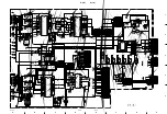
Page 82: ...GB_STC TO 8 8 3 3V 2 DIG 3 3V 2 DIG 3 3V 2 DIG SRX_4W TO 2 8 4 8 STX_4W TO 4 8 5 8 TO 4 8 5 8 CS_SC TO 4 8 TO 8 8 SCK_4W PIHS PICLK POCLK POHS POVS R7 R6 R5 R4 R3 R2 R1 R0 G7 G6 G5 G4 G3 G2 G1 G0 B7 B6 B5 B4 B3 B2 B1 B0 RR7 RR6 RR5 RR4 RR3 RR2 RR1 RR0 RL7 RL6 RL5 RL4 RL3 RL2 RL1 RL0 GR7 GR6 GR5 GR4 GR3 GR2 GR1 GR0 GL7 GL6 GL5 GL4 GL3 GL2 GL1 GL0 BR7 BR6 BR5 BR4 BR3 BR2 BR1 BR0 BL7 BL6 BL5 BL4 BL3 ...

Page 83: ...B 1608 16V 0 1 B 1608 16V 0 1 B 1608 16V 0 1 B 1608 16V 0 1 B 1608 16V 0 1 B 1608 16V 0 1 B 1608 16V 0 1 B 1608 16V 0 1 B 1608 16V 0 1 B 1608 16V 0 1 B 1608 16V 0 1 B 1608 16V 0 1 B 1608 16V 0 1 B 1608 16V 0 1 B 1608 16V 0 1 B 1608 16V 0 1 B 1608 16V 0 1 B 1608 16V 0 1 B 1608 16V 0 1 B 1608 16V 0 1 B 1608 16V 0 1 B 1608 16V 0 1 B 1608 16V 0 1 B 1608 16V 0 1 B 1608 16V 0 1 B 1608 16V 0 1 B 1608 16V...

Page 84: ... 16W 51 CHIP 1 16W 100 CHIP RN CP 1 16W 270 CHIP 1 16W 2 2k CHIP 1 16W 220 CHIP 1 16W 39k CHIP 1 16W 6 8k B CHIP 16V 0 1 B CHIP 16V 0 1 B CHIP 16V 0 1 B CHIP 25V 0 01 B CHIP 16V 0 1 B CHIP 16V 0 1 B CHIP 16V 0 1 B CHIP 16V 0 1 B CHIP 16V 0 1 B CHIP 16V 0 1 B CHIP 16V 0 1 B CHIP 16V 0 1 B CHIP 16V 0 1 B CHIP 16V 0 1 B CHIP 16V 0 1 B CHIP 16V 0 1 B CHIP 16V 0 1 B CHIP 16V 0 1 AL CP 6 3V 47 B CHIP 25...

Page 85: ...CHIP 16V 0 1 B CHIP 16V 0 1 B CHIP 16V 0 1 B CHIP 16V 0 1 B CHIP 16V 0 1 B CHIP 16V 0 1 B CHIP 16V 0 1 B CHIP 16V 0 1 B CHIP 16V 0 1 B CHIP 16V 0 1 B CHIP 16V 0 1 B CHIP 16V 0 1 B CHIP 16V 0 1 B CHIP 16V 0 1 B CHIP 16V 0 1 B CHIP 16V 0 1 B CHIP 16V 0 1 B CHIP 16V 0 1 CH CHIP 470p B CHIP 16V 0 1 B CHIP 16V 0 1 CH CHIP 10p B CHIP 16V 0 1 B CHIP 16V 0 1 B CHIP 16V 0 1 CH CHIP 10p B CHIP 16V 0 1 B CHI...

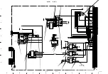
Page 86: ...V 0 1 6 3V 100 B 16V 0 1 B 16V 0 1 B 16V 0 1 B 16V 0 1 B 16V 0 1 B 16V 0 1 B 16V 0 1 B 16V 0 1 B CHIP 16V 0 1 B CHIP 16V 0 1 B CHIP 16V 0 1 RGB_B TO 2 8 RGB_A CLKIN 2 TO 2 8 3 3V 2 DIG STX SCK DIS OSD TO 2 8 CS_OSD STX_4W SCK_4W TO 2 8 TO 2 8 TO 1 8 4 8 8 8 TO 4 8 TO 1 8 4 8 SYS_RESET 3 3V 2 DIG TO 2 8 DE VSYNC HSYNC DUAL PDWNL BB7 BB6 BB5 BB4 BB3 BB2 BB1 BB0 GB7 GB6 GB5 GB4 GB3 GB2 GB1 GB0 RB2 RB...

Page 87: ...IP 1 16W 680 CHIP 1 16W 4 7k CHIP 1 16W 680 CHIP 1 16W 560 CHIP 1 16W 680 CHIP 1 16W 100 CHIP 1 16W 100 CHIP 1 16W 100 RN CP 1 16W 7 5k CHIP 1 16W 100 CHIP 1 16W 47 CHIP 1 16W 10k CHIP 1 16W 100 CHIP 1 16W 680k CHIP 1 16W 47 RN CP 1 16W 1k CHIP 1 16W 3 9k CHIP 1 16W 680k CHIP 1 16W 47 RN CP 1 16W 27k CHIP 1 16W 2 2k CHIP 1 16W 0 CHIP 1 16W 100 CHIP 1 16W 47 CHIP 1 16W 100 CHIP 1 16W 100 2SA1037AK ...

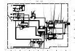
Page 88: ...00k DTC144EE 2SA1462 2SA1462 2SA1462 0UH DAN202K DAN202K 1SS387 B CHIP 0 1 B CHIP 0 1 CH CHIP 470p B 16V 0 1 B CHIP 25V 0 022 B CHIP 25V 0 022 B CHIP 25V 0 022 B CHIP 16V 0 1 B CHIP 16V 0 1 CH CHIP 22p CH CHIP 220p CH CHIP 100p B CHIP 16V 0 1 B CHIP 16V 0 1 B CHIP 16V 0 1 B CHIP 16V 0 1 CH CHIP 220p B CHIP 25V 0 01 B CHIP 25V 0 01 B CHIP 16V 0 1 B CHIP 16V 0 1 B CHIP 16V 0 1 B CHIP 16V 0 1 B CHIP ...

Page 89: ...1 B CHIP 16V 0 1 B CHIP 16V 0 1 B CHIP 16V 0 1 B CHIP 16V 0 1 SN74LV123APSR AL CP 10V 220 AL CP 16V 330 AL CP 16V 330 AL CP 10V 220 AL CP 6 3V 100 MSM56V16160F SYSTEM IC CXD9606Q CHIP 22µH CHIP 22µH CHIP 10µH CHIP 10µH 3 3V 2 DIG PIFLD TO 1 8 RGB_H RGB_V VID_V VID_H IP_HD TO 7 8 PLLHD 3 3V 2 DIG PICLK SYS_VS SYS_HS RGB_STC RGB_ATS 3 3V 2 DIG 3 3V 2 DIG 3 3V 2 DIG SDA_HS SCL_HS SYS_RESET CLP TO 7 8...

Page 90: ...8 1 2 3 4 5 6 7 8 9 10 11 12 13 14 24 23 22 21 20 19 18 17 16 15 CLAMP MATRIX CLAMP OFFSET2 CB CR SW Y OFFSET1 SW SW DC REST BS DL LPF AMP SET UP SHARP NESS SHARP NESS HALFTONE CLAMP CLAMP MATRIX SW SYNC SEPA NOISE DET MASK V INTEC V SEPA V C D H C D H VCO AFC SUB COLOR BASE BAND SW 1H DL LPF P N DEMO BPF TOF AGC SW C MUTE COLOR SYSTEM C Y CVBS YC SELECT P N ID DE EMPHASIS SECAM DEMO BELL BLACK AD...

Page 91: ...White Level 3 C2 White Level 4 C3 Black Level 1 C4 Black Level 2 C5 Black Level 3 C6 Black Level 4 C7 PCO OVcc Bias FILIN DAGnd YOUT DAVcc COUT DAREF 1BIAS ADGnd ADVcc TE1 TE0 MODE1 MODE0 ADCLK DGnd NC CLC CLOUT VIN RBT RTP NC D3 NC D2 NC D1 NC D0 Bypass VH DGnd DVcc Fsc PAL N M PAL NTSC Comb BPF B 1 8 8 8 MSM56V16160F 10TS K IC603 IC802 IC803 IC804 34 CKE 35 CLK 18 CS 17 RAS 16 CAS 15 WE 36 UDQM ...

Page 92: ...XT CEXT CEXT 1 1 Q 2Q 2 CLR 2B 2A 1A 1B 1 CLR 1Q 2Q CEXT 2 2 REXT CEXT GND 11 10 9 2 3 4 5 6 7 8 CLR Q Q CLR Q Q B 3 8 SI 3025LSA IC201 IC202 IN MIC VC _ TSD VOUT IN PTR GND 3 7 8 5 6 1 4 B 4 8 SN74CBTD3306 IC1019 10E 1 8 VCC 1A 2 1B 3 GND 4 6 2B 5 2A 7 2OE VDD 2 VSS CD 4 5 OUT 1 VREF DELAY B 4 8 S 80828CNNB B8NT2G IC1005 B 4 8 S 80842CNNB B83T2G IC1020 B 4 8 RS5C348A IC1003 32kHz OUTPUT CONTROL O...

Page 93: ...LAMP DIGITAL II LOCK ROW LATCH DISPLAY LATCH ADDR DEC ADDR DECODER POR CKT V I REF SS CTR SERIAL CONTROL PORT ROW COMMAND PROCESSOR ADDRESS MUX DISPLAY RAM CHARACTER GENERATOR OUTPUT LOGIC STATUS REG TEST REG 7 VIDEO 8 CSYNC LOCK SIG PG SLICE LEVEL COMP SYNC MSYNC 9 LPF RREF 5 HIN DATA CLK RECOVERY FLD MSGR CW DOT CLK CHAR CLK LS SFLD SLS 10 VSS A 11 FEW VW V IN INTRO SMS DATA LINE DATA BUS AW 13 ...

Page 94: ...A111 TX MA111 TX MA111 TX UDZSTE 175 6B UDZSTE 175 6B 1608 25V 1608 50V 1608 50V 6 3V 47 LED_GREEN LED_RED STBY3 3V SIRCS STBY 5V 3 2 1 4 3 2 1 GND SIRCS STBY3 3V LED_GREEN LED_RED GND STBY 5V TO B BOARD CN1004 MENU OK UP DOWN POWER POWER GND KEY_SENSE STBY5V CN8651 4P BRN 4 3 2 1 R8656 1 8k CHIP 1 10W S8653 R8651 33k CHIP 1 10W S8652 C8652 CH 10p 50V 1608 C8651 B 4 7 10V 3216 S8651 R8652 10k CHIP...

Page 95: ...6W 150 CHIP 1 16W 100 CHIP 1 16W 150 CHIP 1 16W 150 CHIP 1 16W 150 CHIP 1 16W 0 CHIP 1 16W 0 CHIP 1 16W 47 CHIP 1 16W 47 CHIP 1 16W 47 CHIP 1 16W 47 CHIP 1 16W 47 CHIP 1 16W 47 CHIP 1 16W 47 CHIP 1 16W 47 CHIP 1 16W 47 CHIP 1 16W 47 CHIP 1 16W 220 CHIP 1 16W 220 CHIP 1 16W 47 CHIP 1 16W 47 CHIP 1 16W 2 2k CHIP 1 16W 2 2k CHIP 1 16W 2 2k CHIP 1 16W 2 2k CHIP 1 16W 47 CHIP 1 16W 47 CHIP 1 16W 47 CHI...

Page 96: ...SC2412K 2SC2412K 0UH 0UH 0UH 0UH 0UH 0UH 0UH 0UH B CHIP 16V 0 1 B CHIP 16V 0 1 B CHIP 16V 0 1 B CHIP 16V 0 1 B CHIP 16V 0 1 B CHIP 16V 0 1 B CHIP 16V 0 1 B CHIP 16V 0 1 B CHIP 25V 0 01 B CHIP 16V 0 1 B CHIP 25V 0 01 B CHIP 25V 0 01 B 16V 0 1 TC74HC4052AF EL UDZSTE 175 6B UDZSTE 175 6B 9P 5P TC7W125FU TC7W125FU TC7W126FU TC7W126FU MAX202CSE TC74HC125AF TC74HC125AF TC74HC125AF TC74HC125AF 02CZ12 TE8...

Page 97: ... 1 16W 12k CHIP 1 16W 22k CHIP 1 16W 22k CHIP 1 16W 22k CHIP 1 16W 22k CHIP 1 16W 10 CHIP 1 16W 2 7k CHIP 1 16W 2 7k CHIP 1 16W 4 7k CHIP 1 16W 4 7k CHIP 1 16W 5 6k CHIP 1 16W 3 3k CHIP 1 16W 5 6k CHIP 1 16W 3 3k CHIP 1 16W 220k CHIP 1 16W 220k CHIP 1 16W 220k CHIP 1 16W 220k CHIP 1 16W 2 2k CHIP 1 16W 2 2k 2SB709A UDZSTE 1733B UDZSTE 1733B UDZSTE 1733B UDZSTE 1733B 1SS387 B CHIP 16V 0 1 B CHIP 25...

Page 98: ... 31 32 33 27 26 25 24 23 22 21 20 19 34 35 36 17 16 15 14 13 12 11 10 18 Vcc ROUT GND N C N C Vcc GOUT GND Vcc BOUT GND GOUT Vcc N C HOUT VOUT GND SW Vin2 Hin2 Bin2 GND N C Gin2 GND Ain2 GND Vin1 Hin1 Bin1 Vcc Gin1 N C Vcc Ain1 Vcc 1 2 3 4 5 6 7 8 9 Q 1 3 SN74HC32APWR IC3023 VCC GND 2Y 2B 2A 1Y 1B 3Y 3A 3B 4Y 4A 4B 1A 1 2 3 4 5 6 7 14 13 12 11 10 9 8 C1 V C1 C2 C2 V T2 OUT R2 IN Vcc GND T1 OUT R1 ...

Page 99: ...BY MUTE _ PWM _ PRE 17 VCC 9 FREQ 1 3 18 20 5 BOOTDIODE 15 VREG 6 BOOT 4 OUT 7 13 NC 16 VCCPOW 14 VCCSIGN VCC Q 1 3 TK15452V IC3010 Q 3 3 TEA6422DT IC3022 VCC STANDBY GND INPUT1 _ INPUT1 OUTPUT1 GND INPUT3 _ INPUT3 OUTPUT3 VCC OUTPUT2 _ INPUT2 INPUT2 1 2 3 4 5 6 7 10 9 8 14 13 12 11 75 Z DRIVER 75 Z DRIVER 75 Z DRIVER 1 5 2 4 3 6 7 8 SELECT A SELECT B 3 2 1 0 3 2 1 0 INH Y1 Y3 Y Y1 Y0 VEE VSS X3 X...

Page 100: ...504 R1503 R1502 R1501 IC1502 2 2 IC1502 1 2 IC1501 C1504 C1503 C1502 C1501 3P CHIP 1 10W 1k CHIP 1 10W 6 8k CHIP 1 10W 2 2k CHIP 1 10W 100 LM35DZ 50V 0 01 CHIP 16V 1 50V 0 01 CHIP 6 3V 100 2 3 2 1 7 6 5 4 8 1 3 AMP TEMP SENSOR CN3012 TO B BOARD GND THERMO STBY 5V S S S ...

Page 101: ... B4 A4 B3 A3 B2 A2 B1 A1 3 3V 5V R42 0 CHIP R36 0 CHIP Q6 2SC1623 T1 L5L6 Q4 2SC1623 T1 L5L6 Q1 2SC1623 T1 L5L6 XX Q5 Q2 2SC1623 T1 L5L6 Q7 2SC1623 T1 L5L6 XX Q3 R62 100k RN CP 1 10W R61 100k RN CP 1 10W R60 0 CHIP R2 75 RN CP 1 10W 75 RN CP 1 10W R1 CN2 10P BLK 2 1 4 3 CN1 10P BLK 2 1 4 3 R33 330 RN CP 1 10W C7 B 0 01 25V 1608 R39 3 3k RN CP 1 10W R41 330 RN CP 1 10W R31 47k RN CP 1 10W R34 47k R...

Page 102: ...VCC 12V PULL_UP AC_DET NC RELAY PS_PD VSUS_ADJ EXT_PD GND_VCC 12V GND_VCC 12V GND_SUS GND_SUS VSUS VSUS NC NC NC GND_VCC 6 5V GND_VCC 16 5V GND_SUS GND_SUS VSUS VSUS NC NC NC GND_VCC 6 5V GND_VCC 16 5V GND_SUS GND_SUS VSUS VSUS GND_VCC 6 5V GND_VCC 16 5V NC NC NC NC GND_SUS GND_SUS VSUS VSUS GND_VCC 6 5V GND_VCC 16 5V NC NC NC NC GND_VCC GND_VCC GND_VCC 6 5V 6 5V GND_VCC GND_VCC STBY3 3V ND_STB NC...

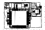
Page 103: ...9 1 FWD 50PX1 9 1 Section 9 Board Layouts Index Board Name Page B 9 2 H1 9 6 H2 9 6 Q 9 4 SP 9 6 S 9 6 U1 FWD 50PX1 9 7 ...

Page 104: ...026 H 1 IC7101 H 1 Q1 B 2 Q2 A 2 Q3 B 1 Q4 B 2 Q5 B 2 Q6 B 2 Q7 B 1 Q8 B 1 Q9 B 2 Q10 B 1 Q11 B 1 Q12 B 2 Q13 B 2 Q14 B 2 Q15 C 2 Q16 C 2 Q17 B 1 Q18 B 2 Q19 B 1 Q20 C 2 Q21 B 1 Q22 B 2 Q23 C 2 Q24 C 2 Q25 C 2 Q26 C 2 Q27 C 2 Q28 C 2 Q29 C 2 Q30 C 2 Q31 C 1 Q32 C 1 Q33 C 1 Q201 C 3 Q203 A 3 Q204 A 3 Q205 B 3 Q206 B 3 Q207 B 3 Q208 A 2 Q209 B 3 Q210 B 2 Q211 B 3 Q212 B 3 Q213 B 3 Q214 B 2 Q215 B 2 ...

Page 105: ...9 3 FWD 50PX1 9 3 B B B B SIDE SUFFIX 11 A 1 2 3 B C D E F G H ...

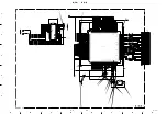
Page 106: ... D 4 D3051 D 4 D3052 E 4 D3053 D 4 D3054 D 4 D3055 E 4 D3056 E 4 D3057 E 4 D3060 D 4 D3061 D 4 D3062 C 4 D3063 C 1 D3064 C 1 D3065 C 1 D3066 D 1 D3067 D 3 D3068 A 4 D3069 A 4 D3070 C 4 D3071 C 4 IC3001 B 4 IC3002 C 4 IC3003 C 3 IC3004 A 3 IC3005 C 3 IC3006 B 3 IC3007 B 2 IC3008 B 1 IC3009 H 2 IC3010 G 2 IC3011 D 3 IC3012 C 1 IC3014 D 1 IC3015 E 1 IC3016 B 2 IC3017 D 4 IC3018 F 2 IC3019 F 2 IC3020 ...

Page 107: ...9 5 FWD 50PX1 9 5 Q Q A 1 2 3 4 B C D E F G H Q B SIDE SUFFIX 11 ...

Page 108: ...51 R8652 R8653 R8654 R8655 R8656 S8651 S8652 S8653 S8654 S8655 S8656 FL9001 J9001 CN9001 H1 A SIDE SUFFIX 11 H1 B SIDE SUFFIX 11 H2 A SIDE SUFFIX 11 H2 B SIDE SUFFIX 11 SP A SIDE SUFFIX 11 S A SIDE SUFFIX 11 R9001 R9002 R9004 R9003 SP B SIDE SUFFIX 11 S B SIDE SUFFIX 11 ...

Page 109: ...9 7 FWD 50PX1 9 7 U1 FWD 50PX1 U1 FWD 50PX1 U1 A SIDE SUFFIX 11 FWD 50PX1 U1 B SIDE SUFFIX 11 FWD 50PX1 ...

Page 110: ......

Page 111: ...A commercial leakage tester such as the Simpson 229 or RCA WT 540A Follow the manufacturers instructions to use these instruments 2 A battery operated AC milliammeter The Data Precision 245 digital multimeter is suitable for this job 3 Measuring the voltage drop across a resistor by means of a VOM or battery operated AC voltmeter The limit indication is 0 75 V so analog meters must have an accurat...

Page 112: ...Printed in Japan Sony Corporation 2004 10 22 B P Company 2004 FWD 50PX1 SY FWD 50PX1N SY E 9 968 064 01 ...

Reviews: