


Reviews:
No comments
Related manuals for 210UPC-V312

Z41 Pro
Brand: Zennio Pages: 2

i3TOUCH E1055 4K
Brand: i3-TECHNOLOGIES Pages: 20

CHTF-05
Brand: K-BUS Pages: 61

L22B1120
Brand: Haier Pages: 57

L20AV6-A0
Brand: Haier Pages: 24

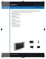
FWD-42LX1
Brand: Sony Pages: 4
FWD-40LX1
Brand: Sony Pages: 2

FWD-32LX1R Mounting Bracket
Brand: Sony Pages: 2

FWD-32LX1R Mounting Bracket
Brand: Sony Pages: 12
FWD-50PX2
Brand: Sony Pages: 48

FWD-42PV1A
Brand: Sony Pages: 50

FWD-50PX1 (English: pgs. 52-97)
Brand: Sony Pages: 112
FWD-50PX2
Brand: Sony Pages: 352

FWD-32LX1R Mounting Bracket
Brand: Sony Pages: 142

FWD-40LX1
Brand: Sony Pages: 144

FWD-32LX1
Brand: Sony Pages: 304

FWD-40LX1
Brand: Sony Pages: 316

FWD-42PV1A
Brand: Sony Pages: 328


