


3-1
FWD-50PX1
Section 3
Troubleshooting
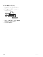
3-1. Judging Method When Image Does
Not Appear
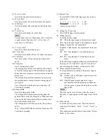
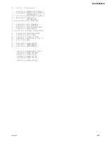
1. Flow chart
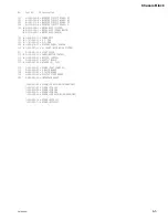
2) The input signal is supplied to the PDP panel correctly.
The LVDS signal is supplied to CN01 of the circuit
board in the center of the PDP panel correctly.
If no image appears when the above conditions are
satisfied, the PDP unit is considered defective.
2. How to find PDP unit trouble
1) The power voltage for the PDP is supplied correctly.
The power voltages are supplied from each connector
on the switching regulator board to the panel.
.
CN8, 9: 6.5 V, 16.5 V, 220 V
.
CN12:
6.5 V, 61 V
.
CN11:
3.3 V, 6.5 V
.
CN10:
12 V
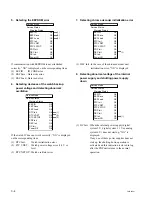
Picture does not appear
Check the indication on the indicator
in the lower right of the front panel. (STAND BY)
2 times
3 times
4 times
5 times
6 times
When error code is detected from the panel.
When temperature increase of the power supply block or temperature
increase inside the unit due to the sensor board is detected.
When a fan stop or failure of the fan drive circuit is detected.
When 3.3 V digital system power voltage decreases (1.6 V or less)
or becomes excess voltage (4 V or more), and 5 V digital system
power voltage decreases (2.5 V or less or becomes excess voltage
(6 V or more)
When 6 V analog system power voltage decreases (3 V or less)
or becomes excess voltage (7.2 V or more)
STBY LED flashes
When the STBY LED does not flash, the power supply circuit is defective.
1
2
1
2
3
0.3 0.3
0.3 0.3
6
3
Summary of Contents for FWD-50PX1 (English: pgs. 52-97)
Page 48: ......
Page 80: ......
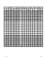
Page 105: ...9 3 FWD 50PX1 9 3 B B B B SIDE SUFFIX 11 A 1 2 3 B C D E F G H ...
Page 107: ...9 5 FWD 50PX1 9 5 Q Q A 1 2 3 4 B C D E F G H Q B SIDE SUFFIX 11 ...
Page 110: ......


