background image

4-73

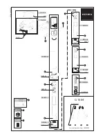
VP-55 BOARD
(SIDE A)

C205

A-1

C207

A-1

C212

B-1

C224

A-3

C225

A-4

C226

B-3

C227

A-3

C228

A-3

C229

B-3

C230

B-3

C235

B-4

C236

A-4

CN234

A-2

D201

B-5

FB261

A-5

FB262

A-5

IC203

A-1

IC204

A-2

IC205

A-3

IC206

B-3

IC207

B-3

IC209

B-4

Q201

A-1

Q202

A-1

Q205

A-5

Q206

A-5

Q207

A-5

Q208

B-5

Q209

B-5

Q210

B-5

Q211

A-5

R216

A-1

R220

A-2

R221

B-1

R222

A-1

R256

A-4

R257

A-4

R228

B-2

R231

A-3

R232

B-2

R233

A-3

R234

A-2

R235

A-3

R238

A-3

R239

A-3

R240

A-3

R241

B-3

R242

B-3

R243

A-2

R244

B-3

R245

A-5

R246

A-5

R247

A-5

R248

B-5

R249

B-5

R250

B-5

R251

B-5

R252

B-3

R253

B-3

PK-55 BOARD
(SIDE A)

BT701

B-2

C705

A-2

C706

A-2

C710

B-3

C711

B-3

C801

D-6

C802

D-6

C811

D-5

C814

E-4

C815

D-5

C816

D-5

C851

E-3

C855

E-3

C861

E-2

C863

D-3

C865

D-3

C866

C-2

C901

D-6

C902

D-7

C913

F-7

C914

E-7

C919

D-6

CN701

D-5

CN702

D-7

CN781

E-5

CN851

C-3

CN901

C-7

D784

E-4

D786

C-1

D787

C-1

D788

B-1

D853

D-3

FB781

F-5

FB786

E-4

IC702

A-3

IC801

E-6

IC803

D-4

IC851

D-3

IC852

D-3

L702

B-3

L801

D-4

L852

E-3

L853

E-2

L901

C-7

L902

D-5

L903

D-5

L904

D-6

Q851

D-3

Q852

D-3

Q853

E-3

Q901

F-1

Q902

E-7

Q903

E-7

Q904

E-7

R703

A-3

R713

B-3

R715

B-3

R724

F-6

R808

E-4

R809

E-4

R810

D-4

R812

E-4

R813

E-4

R814

E-4

R817

E-4

R818

E-4

R821

E-4

R853

E-3

R854

E-3

R864

E-3

R867

E-2

R868

E-2

R869

D-3

R870

D-3

R871

D-3

R872

C-3

R901

D-6

R903

D-6

R908

D-6

R935

E-7

R936

E-7

R940

D-6

R941

F-7

R942

F-7

R946

D-7

R947

D-7

R948

D-7

R949

C-6

R950

D-7

R951

C-6

PK-55 BOARD
(SIDE B)

C803

D-4

C804

D-4

C805

D-4

C806

E-4

C807

E-4

C808

D-4

C810

D-4

C812

E-5

C813

E-4

C852

E-3

C853

E-4

C854

D-2

C856

E-3

C857

D-3

C858

D-3

C859

E-3

C862

E-3

C864

E-2

C903

D-6

C904

E-6

C905

D-7

C906

F-6

C907

F-6

C908

E-7

C909

F-6

C911

F-6

C912

D-6

C915

C-6

C916

D-7

C917

C-6

C918

D-7

D701

B-2

D702

A-3

D703

A-3

D782

F-5

D783

F-5

D785

C-1

D789

F-5

D790

F-4

D854

C-3

D902

E-6

D903

D-7

FB782

E-5

FB783

E-5

FB784

E-5

FB785

E-4

FB787

C-1

FB788

C-2

FB789

C-2

FB790

C-2

FB791

C-2

FB801

D-4

FB802

D-4

FB803

D-4

IC802

D-4

IC901

E-6

IC902

F-7

J781

B-1

L802

E-5

L851

E-4

L905

E-6

Q854

E-3

Q855

D-3

Q856

E-3

Q857

D-3

Q858

D-3

Q859

D-3

Q860

E-3

Q861

D-3

R708

B-2

R712

A-3

R714

A-3

R716

A-6

R717

A-6

R718

A-6

R719

A-6

R720

C-1

R721

A-2

R722

D-1

R723

D-1

R727

B-3

R782

C-2

R787

C-1

R820

D-5

R855

D-3

R856

E-3

R857

E-3

R858

E-3

R859

D-3

R860

D-3

R861

D-3

VP-55 BOARD
(SIDE B)

C201

A-2

C202

A-2

C203

A-3

C204

A-2

C206

B-3

C208

B-2

C209

B-3

C210

B-2

C211

A-3

C213

A-1

C214

B-2

C215

B-2

C231

A-5

C232

A-4

C233

A-4

C234

A-4

C237

B-3

C238

A-3

CN231

A-2

CN232

A-5

CN235

A-1

CN236

B-5

FB201

A-3

FB260

A-5

FB263

A-5

FB264

A-5

IC201

A-3

IC202

A-2

IC208

A-4

IC210

A-4

L201

A-3

L202

A-1

L204

A-5

L205

A-5

L206

A-3

L207

B-3

Q203

A-2

Q204

B-1

R201

A-2

R202

A-1

R203

B-3

R204

A-2

R205

A-3

R206

B-3

R207

A-3

R209

B-3

R210

A-2

R211

B-3

R212

A-1

R213

B-3

R214

B-2

R215

B-2

R217

B-2

R218

B-2

R219

A-1

R223

B-1

R224

B-2

R225

A-2

R227

B-2

R254

A-4

R255

B-4

R258

B-5

R259

B-5

X201

B-4

R956

E-7

R957

D-6

R961

D-6

R962

D-6

R974

C-6

R976

C-6

S707

F-6

S709

F-7

SE701

A-3

T851

D-2

R862

D-3

R863

D-3

R865

D-3

R866

D-3

R873

C-3

R902

D-6

R904

E-6

R905

E-6

R911

F-6

R912

F-6

R913

E-6

R916

F-6

R917

F-6

R919

F-6

R920

E-7

R921

F-6

R922

F-7

R923

E-7

R925

D-6

R927

D-6

R928

E-7

R929

F-7

R931

D-6

R932

F-7

R933

E-7

R934

D-7

R939

E-7

R944

C-6

R945

C-6

R952

D-7

R953

D-7

R954

D-7

R958

D-6

R959

D-6

R960

D-6

R963

C-7

R964

C-7

R966

C-6

R967

C-7

R968

C-6

R969

C-6

R970

D-6

R971

C-6

R972

D-6

R973

C-6

R975

D-6

R977

D-5

S701

A-7

S702

A-6

S703

A-5

S704

D-1

S705

A-2

S706

C-1

S708

D-1

4-76

Summary of Contents for FD Mavica MVC-FD97

Page 1: ...d please refer to page 6 to discriminate the type of LCD System Image device 6 64 mm 1 2 7 type color CCD Lens 10 zoom lens f 6 0 60 0 mm 1 4 2 3 8 inches 39 390 mm 1 9 16 15 3 8 inches when converted into a 35 mm still camera F 2 8 Exposure control Automatic exposure White balance Automatic Indoor Outdoor One push Data system Movie MPEG Still JPEG GIF in TEXT mode Clip Motion TIFF Audio with stil...

Page 2: ...LIST ARE CRITICAL TO SAFE OPERATION REPLACE THESE COMPONENTS WITH SONY PARTS WHOSE PART NUMBERS APPEAR AS SHOWN IN THIS MANUAL OR IN SUPPLEMENTS PUB LISHED BY SONY General Application Sony battery pack NP F330 supplied F550 Power requirements 8 4 V Power consumption During shooting 4 2 W When using the LCD screen 3 8 W When using the finder Operating temperature 0 C to 40 C 32 F to 104 F Storage t...

Page 3: ...LIGHT DRIVE Schematic Diagram 4 53 VF 143 Printed Wiring Board 4 55 VF 143 LCD DRIVE Schematic Diagram 4 57 VF 143 TIMING GENERATOR EVF LCD BACK LIGHT Schematic Diagram 4 59 MA 404 Printed Wiring Board and Schematic Diagram 4 61 AE 25 Printed Wiring Board and Schematic Diagram 4 63 CF 83 Printed Wiring Board and Schematic Diagram 4 65 FU 153 Printed Wiring Board and Schematic Diagram 4 67 4 3 Wave...

Page 4: ...oard 5 47 1 7 System Control System Adjustments 5 48 1 Battery Down Adjustment 5 48 2 ZOOM Center Adjustment 5 49 3 Eye Sensor Adjustment 5 49 4 Eye Sensor Check 5 50 5 Alignment Check FDD Unit 5 50 5 2 Service Mode 5 51 2 1 Adjusting Remote Commander 5 51 1 Used the Adjusting Remote Commander 5 51 2 Precaution upon Using the Adjusting Remote Commander 5 51 2 2 Data Process 5 52 2 3 Service Mode 5...

Page 5: ...sulating tape fully around the leads of the resistor to pre vent electrical shock 1 kΩ 1 W Wrap insulating tape Discharging the Capacitor Short circuit between the positive and the negative terminals of charged capacitor with the short jig about 10 seconds SERVICE NOTE NOTE FOR REPAIR Make sure that the flat cable and flexible board are not cracked of bent at the terminal Do not insert the cable i...

Page 6: ... LCD can be discrimi nated Note About PK 55 board and LCD module discriminate LCD type on the machine and replace the same type FC 85 board CN803 Resistor LCD type PD board value 4 7 kΩ TYPE S PK 55 TYPE S 47 kΩ TYPE C PK 55 TYPE C FC 85 board CN803 1 1 22 22 CPC cover CPC 12 jig J 6082 436 A Volt ohm meter qd pin 4 pin ...

Page 7: ...ve circuit Cause Defective floppy disk The type of floppy disk that cannot be used by this machine is inserted Such as 2DD Data is damaged Unformatted disk or Memory Stick is inserted Abnormality when flash is being charged 1 When failed in the focus initialization Caution Display During Error DRIVE ERROR DISK ERROR MEMORY STICK ERROR Flash LED Flash display Flashing at 3 2 Hz Note The error code ...

Page 8: ...district Light industry district This equipment complies with the EMC standard regulations EN55022 Class B The electromagnetic fields at the specific frequencies may influence the picture and sound of this camera For the Customers in the U S A and Canada For the Customers in Canada NOTICE FOR THE CUSTOMERS IN THE UNITED KINGDOM For the Customers in Germany Attention 4 Operating instructions Before...

Page 9: ...tery pack L series See page 77 for more information about InfoLITHIUM battery pack To remove the battery pack Open the battery cover Slide the battery eject lever rightward and remove the battery pack Be careful not to drop the battery pack when removing it What is InfoLITHIUM InfoLITHIUM is a lithium ion battery pack which can exchange information such as battery consumption with compatible video...

Page 10: ... decreased when using at low temperature using the flash turning the power on off frequently or using the zoom The capacity of the floppy disk or Memory Stick is limited The above figures are as a guide when you continuously record play back by replacing the floppy disk or Memory Stick If sufficient battery remaining time is indicated but the power runs out soon fully charge the battery so that th...

Page 11: ...JECT lever EJECT lock Unrecordable unerasable Recordable erasable Getting started 17 Inserting a Memory Stick Open the Memory Stick cover then push the Memory Stick once lightly Notes If you do not insert the Memory Stick firmly until it clicks a message such as MEMORY STICK ERROR will be displayed Never remove the Memory Stick turn off the power or change the position of the MS FD selector while ...

Page 12: ...e control button and then press the center z To delete the image first select DELETE on the Quick Review screen with b B on the control button and press the center z and then select OK with v V on the control button and press the center z Adjust the brightness with the LCD BRIGHT item in the menu settings page 47 This adjustment does not affect the brightness of the images recorded on the floppy d...

Page 13: ...lide the POWER switch to the right to turn on the power and insert a floppy disk or a Memory Stick See pages 20 to 23 Press DISPLAY to turn on off the indicators on the LCD screen or on the finder These indicators are not recorded See page 89 for a detailed description of the indicators 1 Set the PLAY STILL MOVIE selector to MOVIE 2 Select the recording media using the MS FD selector MS When recor...

Page 14: ...red in the following formats Make sure that applications that support these file formats are installed on your computer Still images other than TEXT mode uncompressed mode and Clip Motion JPEG format Moving images audio MPEG format Uncompressed mode still images TIFF format TEXT mode Clip Motion GIF format ActiveMovie Player DirectShow must be installed to play back moving pictures QuickTime 3 2 o...

Page 15: ...When Put these items into the Extensions folder appears click OK 7 Restart your computer and connect the USB cable B B B B Playback 33 xViewing images For Windows 98 Windows 98SE Windows Me and Windows 2000 Professional users 1 Turn on the power of your computer and allow Windows to load 2 Connect one end of the supplied USB cable to the USB jack mini B on the camera and the other end to the USB c...

Page 16: ...hen using floppy disks Storage destination containing still image moving image TEXT mode image and Clip Motion image data Folder containing E mail mode image data Folder containing VOICE mode audio data B B B B Playback 37 The numerical portions of the following files are the same An image file recorded in E MAIL mode and its corresponding small size image file An audio file recorded in VOICE mode...

Page 17: ...tons images and menus displayed on the LCD screen or on the finder of your camera and modify the settings The operation methods that are frequently used for Advanced operations are described below PLAY STILL MOVIE PLAY To play back or edit images STILL To record still images VOICE images and Clip Motion images MOVIE To record moving images Select Set enter Before performing advanced operations 41 ...

Page 18: ...forming advanced operations 45 CAMERA REC MODE TIFF Records a TIFF uncompressed file in addition to the JPEG file when the MS FD selector is set to MS STILL TEXT Records a GIF file in black and white VOICE Records an audio file with a still image in addition to the JPEG file E MAIL Records a small size 320 240 JPEG file in addition to the selected image size xNORMAL Records an image using the norm...

Page 19: ... sufficient DISK FULL appears on the LCD screen or on the finder and you cannot record any more images If you try to record 3001 images or more on a Memory Stick even if the remaining memory capacity of the Memory Stick is sufficient NO MEMORY SPACE appears on the LCD screen or on the finder and you cannot record any more images In TEXT mode even if you select 1600 ECM the number of images you can...

Page 20: ...ox 7 1600 ECM Approx 5 1024 768 Approx 6 Approx 17 640 480 Approx 12 Approx 34 1 Set the PLAY STILL MOVIE selector to STILL 2 Select FILE REC MODE and then TEXT from the menu 3 Record the image Image size Number of images Floppy disk Memory Stick 1600 1200 Minimum 4 Minimum 25 1600 3 2 Minimum 5 Minimum 28 1600 ECM Minimum 4 1024 768 Minimum 11 Minimum 61 640 480 Minimum 28 Minimum 160 3 2 1 B B B...

Page 21: ...ng the subject stand out against an unclear background or making both the subject and the background stand out clearly Press PROGRAM AE repeatedly to select an aperture value in 9 steps from F2 8 to F11 Shutter speed priority mode For recording a sharp picture of a fast moving subject or recording the flow of motion of a moving subject Press PROGRAM AE repeatedly to select a shutter speed in 17 st...

Page 22: ...or MOVIE 2 Select EFFECT and then P EFFECT from the menu 3 Select the desired mode SOLARIZE The light contrast is clearer and the picture looks like an illustration B W The picture is monochrome black and white SEPIA The picture is sepia toned like an old photograph NEG ART The color and brightness of the picture are reversed as in a negative OFF Does not use the picture effect function 2 3 1 B B ...

Page 23: ...CT The protect indicator appears on protected images To release protection Select OFF in step 2 To release protection If you selected ALL in step 2 select OFF If you selected SELECT in step 2 select the images to be unprotected with the control button then select ENTER In single mode 1 Set the PLAY STILL MOVIE selector to PLAY then display the image to be protected 2 Select FILE PROTECT and then O...

Page 24: ...pied using multiple floppy disks To cancel copying partway Select CANCEL In INDEX mode 1 Select the media using the MS FD selector 2 Set the PLAY STILL MOVIE selector to PLAY then display the INDEX screen 3 Select TOOL and then COPY from the menu 4 Select the media that the image will be copied onto When the MS FD selector is set to FD FD t FD Copies to the floppy disk FD t MS Copies to the Memory...

Page 25: ...ra to a computer using the USB cable you can use the camera as a floppy disk Memory Stick drive of a computer Install the USB driver to the computer beforehand page 31 For Windows 98 Windows 98SE Windows Me and Windows 2000 Professional Users Note When using Windows Me or Windows 2000 Professional see also page 34 1 Connect the camera to the computer using the supplied USB cable 2 Select the drive...

Page 26: ...Memory Stick MagicGate Memory Stick and are trademarks of Sony Corporation MagicGate and are trademarks of Sony Corporation Using your camera abroad Power sources You can use your camera in any country or area with the supplied battery charger within 100 V to 240 VAC 50 60 Hz Use a commercially available AC plug adaptor a if necessary depending on the design of the wall outlet mains b AC L10A L10B...

Page 27: ... recording moving pictures Digital zoom is set to OFF tSet digital zoom to ON at the menu The image is in monochrome You shot the image in TEXT mode tCancel the TEXT mode page 52 The picture effect is set to B W tCancel the B W mode page 60 The image cannot be played back on a computer tConsult the computer or software manufacturer Symptom Cause and or Solution 81 Additional information The image ...

Page 28: ...ion has occurred in the battery pack tContact your Sony dealer or local authorized Sony service facility The POWER ON OFF CHG lamp does not light up when charging a battery pack The AC power adaptor is not connected tConnect the power cord firmly to a wall outlet mains page 10 The battery pack is not installed properly tInstall it properly page 9 Charging of the battery pack is complete Symptom Ca...

Page 29: ...ect indicator I DATE indicator J EV level indicator K Iris Shutter speed indicator L AE lock indicator Focus lock indicator M Recording mode Clip Motion indicator N Image size indicator O Number of recorded images P Remaining disk capacity Remaining memory capacity indicator Floppy disk Memory Stick Q Recording time indicator R Self diagnosis function indicator Recording time indicator S Self time...

Page 30: ...BOARD Page 2 3 2 7 LCD MODULE Page 2 4 2 8 FDD BLOCK ASSEMBLY Page 2 5 2 14 FC 85 BOARD Page 2 7 2 15 CF 83 BOARD Page 2 7 2 9 FU 153 BOARD Page 2 5 2 10 LENS COMPLETE BLOCK ASSEMBLY Page 2 5 2 11 CABINET VP BLOCK ASSEMBLY Page 2 5 2 12 VP 55 BOARD Page 2 6 2 13 LENS BLOCK ASSEMBLY Page 2 6 MVC FD97 SERVICE POSITION CD 311 AND VP 55 BOARDS Page 2 6 SERVICE POSITION FC 85 BOARD Page 2 7 SERVICE POS...

Page 31: ... M2 4 Screw M2 5 Screw M2 6 Clow 7 Top cabinet block assembly 8 Flexible board CN802 0 Flexible board CN301 9 Harness CN301 1 Two plate screws M2 2 Accessory shoe 3 Screw M2 4 Screw M2 5 EVF block assembly 2 VF cabinet assembly 3 Flexible board CN501 1 Screw M2 4 VF lens assembly 2 Two clows 7 Two clows 9 VF 143 board 3 Clow 6 Clow 8 Clow 4 BL illuminator 5 Two LCD cushions 1 Flexible board CN802 ...

Page 32: ... 5 Cabinet rear block assembly 6 Flexible board CN802 7 Six screws 4 Screw 5 Z shield case assembly 8 PK 55 board 2 Flexible board CN781 3 Flexible board CN901 6 Flexible board CN851 1 Harness CN702 Adjustment remote commander CPC 12 jig J 6082 436 A VF 143 board Base VF lens assembly AC IN AC power adaptor Contacting surface ...

Page 33: ... fluorescent tube 6 LCD module SERVICE POSITION PK 55 BOARD AND LCD PANEL Adjustment remote commander CPC 12 jig J 6082 436 A PK 55 board FC 85 board LCD panel Insulating sheet Base Base Cold cathode fluorescent tube AC IN AC power adaptor Cabinet front block assembly Contacting surface ...

Page 34: ...3 1 Harness CN003 5 Harness CN004 2 10 LENS COMPLETE BLOCK ASSEMBLY 2 11 CABINET VP BLOCK ASSEMBLY 3 Screw M2 4 FU 153 board 1 Harness CN002 2 Harness CN001 1 Four screws M2 2 Remove the lens complete assembly in the direction of the arrow 4 Cabinet VP block assembly 2 Screw M2 1 Screw M2 3 Two clows 5 Flexible board MF block ...

Page 35: ... 5 Clow 6 Cabinet LT 8 Flexible board CN232 7 Two flexible board CN231 235 1 Two screws 2 Boss 3 Boss 4 Lens block assembly FU 153 board AC IN AC power adaptor Cabinet LB assembly PK 55 board FC 85 board CD 311 board VP 55 board Base Base Cabinet front block assembly Contacting surface Adjustment remote commander CPC 12 jig J 6082 436 A Cabinet rear block assembly Cabinet VP assembly Lens block as...

Page 36: ...2 703 2 Screw M2 5 Four screws M2 3 USB connector 6 Claw 7 FC 85 board 1 Screw M2 3 CF 83 board Two switches S402 403 Two SS knobs 2 Two claws Adjustment remote commander CPC 12 jig J 6082 436 A FU 153 board FC 85 board CF 83 board VP 55 board AC IN AC power adaptor Top cabinet block assembly Cabinet rear block assembly Cabinet VP assembly Cabinet LB assembly Lens block assembly FDD Contacting sur...

Page 37: ...FDD INTERFACE FDD CONTROL HI CONTROL AUDIO DC DC CONVERTER FU 153 DC IN AE 25 CONTROL SWITCH VP 55 STEDY SHOT CONTROL CF 83 CONTROL SWITCH CD 311 CCD IMAGER STEADY SHOT SENSOR MA 404 MIC AMP PK 54 MODE SWITCH A V OUT LCD DRIVE TIMING GENERATOR BACK LIGHT DRIVE VF 143 LCD DRIVE TIMING GENERATOR BACK LIGHT FLASH UNIT ...

Page 38: ...2 9 E 2 17 FLEXIBLE BOARDS LOCATION FP 171 FP 174 FP 173 FP 177 FP 170 FP 169 FP 166 FP 172 FP 168 FP 335 FP 176 FP 175 ND801 LCD901 Lens assembly VAP assembly LCD902 Control switch block ...

Page 39: ...N1 XRS ON2 SYS DD ON LCD DD ON BATT SIG STB CHARGE HALL AD STRB ON Z SENS RST F SENS RST Z SENS RST F SENS RST PE EN1 PE DIR1A PE DIR1B PE EN0 PE DIR1A PE DIR0B STRB AIN HALL AD HALL DRIVE XSTB FULL PE DAC LEVEL CNTC SP VOL 1 2 SP VOL STRB ON STRB AIN STB CHARGE XSTB FULL ND DRIVE BATT SIG SEE PAGE 4 68 MC XRD MC XWE1 FLOPPY DISK DRIVE UNIT FDD DATA ACC FUNCTION KEY IC404 HI CONTROL SEE PAGE 4 32 ...

Page 40: ... 87 18 45 46 7 8 44 12 13 40 26 24 39 31 29 6 11 25 30 19 20 21 22 16 17 29 47 99 SYS DD ON LCD DD ON EVF DD ON VREF 2 5V V REF 2 5V VCC INA INB INC IND V REF 2 5V POW CONT CTL B CTL C D VCC OUT OUT A IN A SCP A OUT B IN B SCP B OUT C IN C SCP C OUT D IN D SCP D RT CT L007 Q003 SWITCHING L005 Q002 SWITCHING L004 SWITCHING Q001 4 3 1 5 2 6 8 T001 DC DC CONV TRANS 4 9V D1 8V REG Q005 007 VREF 2 5V L...

Page 41: ...IC501 MC CAM SH DSP SEE PAGE 4 23 IC185 IRIS DRIVE HALL AMP HALL BIAS GAN CONTROL SEE PAGE 4 22 IC102 S H AGC A D CONV SEE PAGE 4 15 IC182 IRIS MECHA SHUTTER DRIVE CAM 7 5V CAM 15V CAM 15V CAM 7 5V CAM 15V 05 CAM 7 5V FOCUS ZOOM MOTOR DRIVE SEE PAGE 4 21 IC183 SEE PAGE 4 22 IC901 VIDEO AMP SEE PAGE 4 19 FB304 FB302 FB301 CAM P 5V L181 Q253 L303 L253 L255 L254 L252 L502 D 3 2V L602 L501 L503 L504 L...

Page 42: ...NEL 6 5V 15 PANEL 15 3V 14 VSH VGH VSH 2 1 12 VCC 3 VSS D903 9 IC802 LCD DRIVE SEE PAGE 4 50 IC902 COM AMP VCO SEE PAGE 4 51 IC801 D A CONVERTER EVR SEE PAGE 4 49 IC901 LCD TIMING GENERATOR SEE PAGE 4 51 LCD901 COLOR LCD MONITOR PANEL UNIT CN901 L802 L801 IC803 BUFFER SEE PAGE 4 49 VSH VGH 1 24 VGL D903 3 VREFH VDD 23 2 VP 55 BOARD IC210 INVERTER SEE PAGE 4 42 IC208 A D CONVERTER SEE PAGE 4 42 IC2...

Page 43: ...ine B B Line J IN OUT direction of B LINE C adjustment for repair Circled numbers refer to waveforms Indicated by the color red Note The components identified by mark 0 or dotted line with mark 0 are critical for safety Replace only with part number specified Note Les composants identifiés par une marque 0 sont critiques pour la sécurité Ne les remplacer que par une pièce portant le numéro spécifi...

Page 44: ...AD4 2 KEY_AD4 3 N C 4 REG_GND 5 REG_GND 2P CN305 1 2 S352 S351 S353 S354 S355 S356 7P CN232 1 GND 2 OUT_1 3 S 3 2V 4 C_RESET 5 S 3 2V 6 OUT_2 7 GND 7P CN102 1 GND 2 OUT_1 3 S 3 2V 4 C_RESET 5 S 3 2V 6 OUT_2 7 GND CCD_OUT HALL PA BATT_UNREG V2 INIT_CHARGE_ON V2 TEMP_OUT ND_CONT DISK REG_GND ZOOM_B BATT XEXT RG GND F_SENS_RST INDEX REG_GND INIT_CHARGE_ON GND RG COMMON REG_GND FOCUS_B V1A GND Z_SENS_...

Page 45: ...T COM GRES SPS GSRT MO1 STRB_PHOTO_ON USB EVF_VCO REG_GND MCLK TST GPCK EX1 STRB_ON EVF_BL_4 75 PF7 SRTL GND VB EX3 UNREG VCC RXD RESET MO2 VCOM VGL A_4 9V INT LANC_IN HCNT VR MODE2 VSS SCLK STB_CHARGE EVF_VG MODE1 RES HI_UNREG VSS SP VGL VCC NC N C SP VG EX2 FDDRF_A BS VREFH VSH EVF_BL VSS VREFL CLS HSY DIO VSH CLD HI_VDD VCC OE VB N C GND VG VSS VB12 GND_GUARD TRACK_00 VGH USB_D TXD CLT VG UNREG...

Page 46: ...it carefully like for the MOS IC In addition ensure that the receiver is not covered with dusts nor exposed to strong light 1 2 3 5 6 4 NO MARK REC PB MODE R REC MODE P PB MODE R14 9 P0 R9 7 P0 R10 4 P0 R8 P0 0 R 0 3 P0 R 0 3 P0 R 0 3 P0 R 7 2 P0 R 7 2 P0 R 7 2 P0 R10 4 P0 R1 3 P0 R1 8 P0 R13 2 P0 R 7 5 P0 R14 9 P0 R7 5 P0 R8 P0 3 6 1 2 5 4 3300 R108 16V 0 1u C108 20V 10u C101 16V 0 1u C106 0 1u C...

Page 47: ...k R153 0 R154 0 01u C164 470k R155 0 015u C157 470k R158 22u C161 UPC6756GR 8JG E2 IC150 1 PASS 2 OUT1 3 AM1 4 Vref1 5 HO1 6 HI1 7 LO1 8 LIA1 9 LIB1 10 GND 11 LIB2 12 LIA2 13 LO2 14 HI2 15 HO2 16 Vref2 17 AM2 18 OUT2 19 CRST 20 VCC 0 015u C156 6 3V 22u C165 15k R160 SE153 XX 1 2 3 4 SE152 XX 1 2 3 4 1 A YAW SENS PITCH SENS PITCH SENS YAW SENS PITCH YAW IC150 2 4 5 8 7 6 E 05 B CD 311 BOARD 2 2 9 3...

Page 48: ... For Printed Wiring Board VP 55 board is four layer print board However the patterns of layers 2 to 3 have not been included in the diagram There are a few cases that the part isn t mounted in this model is printed on this diagram See page 4 76 for printed parts location Chip transistor E B C A K K 1 3 4 5 1 3 4 5 1 5 4 1 3 ...

Page 49: ...R205 6 3V 4 7u C237 0 47u C210 0 01u C236 2SB1218A QRS TX Q209 XX C217 15k R217 15k R211 10V 10u C211 0 1u C234 22k R239 NJM324V TE2 IC204 1 2 3 4 5 6 7 8 9 10 11 12 13 14 0 001u C206 22k R238 0 01u C235 0 5 47k R227 0 5 1k R204 0 5 100k R233 NJM3403AV TE2 IC205 1 2 3 4 5 6 7 8 9 10 11 12 13 14 0 5 10k R215 10uH L207 47k R253 10k R250 0 1u C238 X201 12MHz 1 2 3 22k R241 3300p C227 4V 4 7u C214 100...

Page 50: ... 44 For Printed Wiring Board PK 55 board is four layer print board However the patterns of layers 2 to 3 have not been included in the diagram There are a few cases that the part isn t mounted in this model is printed on this diagram See page 4 76 for printed parts location Chip transistor E B C 3 2 1 4 5 10 6 1 2 3 4 5 K K A K K A K K A 4 3 5 1 4 3 5 1 10 MOVIE PLAY PLAY STILL MOVIE BT701 BATTERY...

Page 51: ...H A V OUT LCD DRIVE LCD TIMING GENERATOR BACK LIGHT DRIVE PK 55 4 45 4 46 CONTROL DISPLAY POWER ON OFF CHARGE POWER FLASH FLASH AV OUT VOLUME VOLUME LCD ON OFF 5 4 1 2 3 1 2 3 5 4 K K A K K A K K A K K A 1 2 3 6 5 4 9 8 7 ...

Page 52: ...89 MAZT082H08S0 D790 LND782 FLAME_GND MAZT082H08S0 D782 FB786 FB784 1 A REG_GND PANEL_ 15 3V PANEL_6 5V S707 S709 6P CN781 6 LANC_SIG 5 XLANC_JACK_IN 4 EXT_STB_ON 3 LANC_DC 2 JACK_GND 1 JACK_GND REG_GND D_3 2V PANEL_3 2V PANEL_4 9V FLASH POWER ON OFF VOLUME VOLUME PLAY STILL MOVIE POWER LED GREEN HDO XHI_SCK VG BL_UNREG XPWR_SW PANEL_B Y PANEL_3 2V KEY_AD1 PANEL_Y XCAM PB_SW XCS_PANEL_D A EVER_3 2...

Page 53: ... COM_AMP 35 COM_BLK_LVL 36 COM_BLK 37 XTEST 38 BRIGHT 39 CONTRAST 40 COM_OUT 41 SUB_CON_B 42 SUB_CON_R 43 VCC1 44 OSD_B 45 OSD_G 46 OSD_R 47 BLACK_IN 48 0 01u C803 0 1u C802 22k R808 P_4 9V 10k R821 100k R820 BL_LEV MB40D001PFV G BND ER IC801 1 BRIGHT 2 COLOR 3 BRT_R 4 BRT_B 5 CONT 6 RGB_AMP 7 COM_ADJ 8 VCO 9 V COM 10 BL_LEVEL 11 BRT_TST 12 P_MUTE 13 VDD 14 VCC 15 H_REV 16 V_REV 17 NTSC 18 COMTST ...

Page 54: ...0 1u 680k R912 120k R911 XX R909 REG_GND V COM VCO FRPT VR VG VB COM O FRPV 0 5 R927 0 R951 0 R960 0 R962 0 R939 0 R959 0 R958 0 R957 0 R949 0 R961 0 R940 0 1u C904 XX D901 R913 47 R974 47 R976 47 R975 47 R971 47 R973 47 R972 0 R967 0 R968 0 R948 0 R963 0 R964 0 R954 0 R956 PANEL_ 15 3V PANEL_4 9V PANEL_3 2V PANEL_13 2V PANEL_V 0 R970 0 R969 0 1u C919 C903 COMTST 2SD2216J QR K8 SO Q901 2SB1462J QR...

Page 55: ... 9V UN9213J K8 SO Q859 1800 R867 0 022u C857 XX C860 0 01u C858 NJM2406F TE2 IC852 1 2 3 4 5 T851 1 2 3 4 5 6 10 BL_UNREG 120 R873 0 5 10k R860 1u C862 FP216 TL Q860 5 1 2 4 3 LND855 SHIELD_GND LND852 SHIELD_GND 0 5 1800 R861 2SD2216J QR K8 SO Q858 C864 0 015u TL5001CD E2 IC851 1 OUT 2 VCC 3 FB 4 IN 5 SCP 6 DTC 7 RT 8 GND UN9214J K8 SO Q851 4700 R859 UN9213J K8 SO Q853 0 22u C853 XX D852 FP102 TL ...

Page 56: ...ries For Printed Wiring Board VF 143 board is six layer print board However the patterns of layers 2 to 5 have not been included in the diagram There are a few cases that the part isn t mounted in this model is printed on this diagram See page 4 77 for printed parts location Chip transistor E B C 9 10 11 7 5 1 2 3 4 6 5 4 1 3 1 2 4 3 5 10 6 1 3 5 4 4 6 1 3 A K 1 2 3 4 5 6 8 ...

Page 57: ... XSCK 20 SI 21 SO 22 XCS 23 VDD_A 24 GND 0 01u B C520 XX R529 0 1u C506 XX R525 39k R521 47k R520 XX R511 XX R512 XX Q504 0 R510 XX R506 10u 6 3V C521 6 3V 10u C501 0 01u B C502 CPT 182S C TSL BCD Q501 CL 200IR X TSL BCD D501 IC501 XX 1 2 3 4 5 6 7 8 2SD1622 ST TD Q503 1 10W 56 R505 2SC5376F B TPL3 Q502 680k R504 22k R501 22k R502 3216 1 8W 10 R503 VXO VCO EVF_BL_GND EVF_BL_4 75V EVF_3 1V EVF_GND ...

Page 58: ...27 H 009 L 12 BLK 13 SLFR 14 HST2 15 STBY 16 CLR 17 EN 18 VST 19 VDD 20 VCK2 21 VCK1 22 HST1 23 HCK2 24 HCK1 25 VD 26 LCX024 H 005 L 27 XHD 28 FRP 29 FLDO 30 SH4 31 VSS 32 SH1 33 SH2 34 SH3 35 XCLP 36 HD 37 SLYT 38 HP4 39 RPD 40 VSS 41 CKO 42 CKI 43 VDD 44 TST4 45 XVD 46 HP1 47 HP2 48 HP3 C624 0 33u F 1T369 01 T8A D602 C621 10u 6 3V EVF_GND EVF_12 0V EVF_BL_4 75V EVF_BL_GND VXO SHA SHR SHB SHG FRP...

Page 59: ...1 2 3 4 5 6 7 8 0 1u C304 1u C303 XX C301 C305 1u 1200 R304 100 R303 XX C302 2P CN305 1 MIC SIG 2 MIC GND 6P CN303 1 2 3 4 5 6 5P CN306 1 2 3 4 5 180 R302 RV001 S001 1 2 3 4 1 A XRS_ON1 REG_GND REG_GND D_3 2V N C A_4 9V ZOOM_SW_AD KEY_AD4 MIC_SIG MIC_GND KEY_AD4 XRS_ON2 D_3 2V UNREG_GND ZOOM_SW_AD XRS_ON1 UNREG_GND XRS_ON2 REG_GND KEY_AD4 MIC_GND T CONTROL SWITCH W ZOOM SHUTTER BLOCK MIC MIC901 2 ...

Page 60: ...inted on this diagram See page 4 77 for printed parts location SPOT METER WHITE BALANCE PROGRAM AE PROGRAM AE PROGRAM AE ONE PUSH WHITE BLANCE 33k R351 1800 R355 4700 R353 2700 R354 6800 R352 S353 S352 5P CN351 1 2 3 4 5 S354 S351 S355 S356 LND351 FRAME_GND XX D351 LND352 FRAME_GND 1 A REG_GND N C KEY_AD4 PROGRAM AE REG_GND KEY_AD4 PROGRAM AE PROGRAM AE WHITE BALANCE ONE PUSH WHITE BALANCE SPOT ME...

Page 61: ...nted in this model is printed on this diagram MACRO FOCUS AUTO r MANUAL STEADY SHOT ON r OFF S403 2 1 3 4 5 6 7 S401 S402 2 1 3 4 5 6 7 6P CN401 1 2 3 4 5 6 R401 33k LND401 FDD_REG_GND LND402 FDD_REG_GND XX D401 XX D402 XX CN402 1 2 3 4 5 6 1 A KEY_AD0 REG_GND REG_GND D_3 2V KEY_AD3 FOCUS_B FOCUS_A D3 2V FOCUS_B FOCUS_A NC GND NC THROUGH THE CONTROL SWITCH CF 83 BOARD REF NO 2 000 SERIES XX MARK N...

Page 62: ...BATT_SIG 3 BATT_GND 4 DC_PACK_SW FB001 0 022u C001 12P CN004 12 11 10 9 8 7 6 5 4 3 2 1 0 R008 3P CN001 1 ACV_UNREG 2 ACV_GND 3 BATT XEXT F004 1 4A 32V 1M R006 FB003 1k R001 F001 1 4A 32V F003 1 4A 32V SSM3K03FE TPL3 Q004 1SS357 TPH3 D002 47k R019 SSM3K03FE TPL3 Q005 XX C003 LND001 STATIC_GND F002 1 4A 32V MAZT082H08S0 D003 0 R021 MA8120 TX D001 F005 1 4A 32V LND002 STATIC_GND FB002 1k R004 R020 1...

Page 63: ...MS CD 311 BOARD IC101 1 2 3 REC 104 µsec 8 0 Vp p 1 IC101 4 5 6 REC 104 µsec 8 0 Vp p 2 IC101 8 REC 104 µsec 1 0 Vp p 3 IC101 qf REC 18 4 MHz 17 1 MHz 17 1 MHz 5 0 Vp p 4 IC101 qg REC 5 0 Vp p 5 IC101 qh REC 4 2 Vp p 6 ...

Page 64: ...3 IC802 0 REC PB 4 IC802 w REC PB 5 IC802 ws REC PB 6 IC802 wf REC PB 7 IC901 REC PB 8 IC901 ef REC PB 500 mVp p 300 mVp p 250 mVp p 4 6 Vp p 4 6 Vp p 4 6 Vp p H IC851 1 REC PB H H 3 0 Vp p IC904 ej REC PB 2H 2H 9 H V 2H 4 8 Vp p q 6 0 Vp p 3 0 Vp p 11 7 MHz 480 MHz PK 55 BOARD 4 71 ...

Page 65: ... REC PB 5 IC502 ws REC PB 6 IC502 wf REC PB 7 IC502 wl REC PB 8 IC601 qg REC PB 480 mVp p 300 mVp p 200 mVp p 8 8 Vp p 8 8 Vp p 8 8 Vp p H IC603 ra REC PB V H H 1 5 Vp p IC603 wj REC PB 2H 2H 2H 68 µsec 9 H 2H 3 0 Vp p q qa IC603 rg REC PB 2 2 Vp p 3 0 Vp p 3 0 Vp p 16 5 MHz 4 72 ...

Page 66: ...B 3 C150 C 3 C151 C 2 C152 C 2 C153 C 2 C156 C 2 C157 C 3 C158 C 3 C159 C 3 C162 B 2 C163 B 3 C164 B 3 CN101 A 1 CN102 B 1 IC101 B 2 IC150 C 3 L101 B 2 Q101 A 2 Q102 B 2 R101 B 1 R102 A 1 R103 A 1 R104 A 1 R105 A 2 R106 A 2 R107 A 2 R108 B 3 R109 B 3 R110 A 2 R150 C 3 R151 C 2 R152 C 2 R153 C 3 R154 C 2 R155 B 2 R156 C 2 R157 B 3 R158 B 3 R159 B 2 R160 B 3 SE150 C 2 SE151 C 2 4 73 4 73 ...

Page 67: ...C907 F 6 C908 E 7 C909 F 6 C911 F 6 C912 D 6 C915 C 6 C916 D 7 C917 C 6 C918 D 7 D701 B 2 D702 A 3 D703 A 3 D782 F 5 D783 F 5 D785 C 1 D789 F 5 D790 F 4 D854 C 3 D902 E 6 D903 D 7 FB782 E 5 FB783 E 5 FB784 E 5 FB785 E 4 FB787 C 1 FB788 C 2 FB789 C 2 FB790 C 2 FB791 C 2 FB801 D 4 FB802 D 4 FB803 D 4 IC802 D 4 IC901 E 6 IC902 F 7 J781 B 1 L802 E 5 L851 E 4 L905 E 6 Q854 E 3 Q855 D 3 Q856 E 3 Q857 D ...

Page 68: ... C610 A 4 C611 A 4 C612 A 5 C613 A 4 C614 B 4 C615 A 3 C625 B 6 C626 B 6 C628 B 6 C629 C 2 C630 B 6 CN601 C 2 D601 B 5 D604 C 6 IC503 B 4 IC601 A 4 IC602 C 2 IC604 C 2 L504 B 4 L601 C 4 L604 B 6 L605 B 7 Q601 B 3 Q602 B 4 Q603 B 4 Q604 B 4 Q605 B 6 R532 C 3 R510 C 3 R601 B 3 R602 A 4 R603 B 3 R604 A 4 R605 A 5 R606 A 4 R607 A 5 R608 A 4 R609 A 4 R610 A 4 R611 B 5 R612 A 3 R613 A 3 R614 B 5 R615 A ...

Page 69: ...not be saved due to defective EEPROM or when the EEPROM cannot be removed or in stalled save the data from the same model of the same destination and download it PC Save the EVR data to a personal computer Download the saved data to a machine Procedure 1 Save the EVR data of the machine in which a board is going to be replaced Download the saved data after a board is replaced Machine after a board...

Page 70: ...nitialization of D page data z z 7 B D E F page data Initialization of 7 B E F page data z z Video Video sync level adj z z z z z Video burst level adj z z z z z Camera Hall adj z z z z z Flange back adj z z z z F No standard data input z z z z Mechanical shutter adjustment z z z z Light level adj z z z z z Auto white balance standard data input z z z z z White balance ND filter compensation z z z...

Page 71: ...o white balance adjustment check White balance adjustment check For checking the flange back White balance adjustment For connecting the adjustment remote commander For adjusting the LCD block Dynamic inspection disk with LCD adjustment signal PC with Windows installed FDD head cleaning Note 1 For adjusting the flange back For the battery down adjustment Fig 5 1 1 J 1 J 6 J 2 J 3 J 4 J 5 J 7 J 8 J...

Page 72: ... power ON Mode 1 Select page 0 address 01 and set data 01 2 Select page D address 10 set data 00 and press the PAUSE button of the adjusting remote com mander 3 Select page 0 address 01 and set data 00 1 1 3 Discharging of the Flashlight Power Supply The capacitor which is used as power supply of flashlight is charged with 200 V to 300 V voltage Discharge this voltage before start ing adjustments ...

Page 73: ... CN702 CN703 CN182 CN401 CN801 CN803 CN401 A V OUT Jack CN702 CN851 CN901 CN701 PK 55 BOARD To LCD PANEL CPC 12 jig J 6082 436 A To LCD BACK LIGHT SPEAKER CN101 LENS UNIT MF UNIT CN102 CN101 CN236 CN232 CN231 CN234 CN235 CD 311 BOARD VP 55 BOARD CF 83 BOARD Audio black Vectorscope Color monitor Video yellow Terminated 75 Ω FC 85 BOARD CN183 CN003 MIC UNIT Adjusting Remote Commander CN002 AC power ...

Page 74: ...r chart Standard picture frame Remove the color bar chart from the pattern box and insert a clear chart in its place Do not perform zoom operations dur ing this time 3 Chart for flange back adjustment Join together a piece of white A0 size paper 1189mm 841 mm and a piece of black paper to make the chart shown in Fig 5 1 8 Note Use a non reflecting and non glazing vellum paper The size must be A0 o...

Page 75: ...woody board A 2 530 mm woody board B 2 500 mm woody board C 1 1000 mm 1026 mm 1026 mm 1000 mm 1000 mm 1030 mm 2 Apply black mat paint to one side of woody board A and B 3 Attach background paper J 2501 130 A to woody board C 4 Assemble so that the black sides and the background paper side of woody board A B and C are internal Fig 5 1 10 Fig 5 1 9 woody board A woody board B woody board B woody boa...

Page 76: ...ddresses is the initial value If not change the data to the initial value Processing after Completing Modification of D Page Data Order Page Address Data Procedure 1 2 00 29 2 2 01 29 Press PAUSE button 3 D Page Table Note 1 Fixed data 1 Initialized data Refer to 1 Initializing of D Page Data Note 2 Fixed data 2 Modified data Refer to 2 Modification of D Page Data Address Initial value Remark 00 t...

Page 77: ...t page 0 address 01 and set data 01 2 New data for changing are not shown in the tables because they are different in destination When changing the data copy the data built in the same model Note If copy the data built in the different model the camcorder may not operate 3 When changing the data press the PAUSE button of the adjustment remote commander each time when setting new data to write the ...

Page 78: ...Table Note 1 Fixed data 1 Initialized data Refer to 1 Initializing of B E F 7 Page Data Note 2 Fixed data 2 Modified data Refer to 2 Modification of B E F 7 Page Data Address Initial value Remark 4F 00 White balance ND filter compensation 50 00 51 03 Color reproduction adj 52 E9 ND filter ON 53 63 54 83 55 D5 56 FE 57 73 58 45 59 00 Auto white balance standard data input 5A 14 Mechanical shutter a...

Page 79: ...Initial value Remark A0 00 Mixed color cancel adj A1 00 A2 00 A3 00 A4 to AB Fixed data 1 Initialized data AC 80 Steady shot adj 2 AD 80 Steady shot adj 1 AE to AF Fixed data 1 Initialized data B0 to FF Fixed data 2 ...

Page 80: ...F 82 0F 83 FF 84 0F 85 FF 86 0F 87 FF 88 0F 89 FF 8A 0F 8B FF CCD white defect compensation 8C 0F 8D FF 6 7 Page Table Note 1 Fixed data 1 Initialized data Refer to 1 Initializing B E F 7 Page Data Note 2 Fixed data 2 Modified data Refer to 2 Modification of B E F 7 Page Data Address Initial value Remark 8E 0F 8F FF 90 0F 91 FF 92 0F 93 FF 94 0F 95 FF 96 0F 97 FF 98 0F CCD white defect compensatio...

Page 81: ...ter Completing Adjustments Order Page Address Data Procedure 1 5 F1 00 2 0 01 00 A H Fig 5 1 11 Fig 5 1 12 1 3 VIDEO SYSTEM ADJUSTMENTS 1 Video Sync Level Adjustment Adjust the sync level of the composite video signal output Mode PLAY Signal Arbitrary Measurement Point Video terminal of A V OUT jack 75 Ω terminated Measuring Instrument Oscilloscope Adjustment Page F Adjustment Address 81 Specified...

Page 82: ...ing data setting before the camera system ad justments Data setting method Order Page Address Data Procedure 1 0 01 01 2 E 43 10 Press PAUSE button 3 E 8F 00 Press PAUSE button 4 B 67 00 Press PAUSE button After completing the camera system adjustments release the data setting Order Page Address Data Procedure 1 0 01 01 2 E 43 08 Press PAUSE button 3 E 8F 11 Press PAUSE button 4 B 67 85 Press PAUS...

Page 83: ...ss PAUSE button 4 Perform Data setting during camera system adjustment Refer to page 5 14 5 6 94 15 6 6 95 7D 7 6 01 6D Press PAUSE button Note 3 8 6 02 Check the data changes to 01 9 6 01 00 Press PAUSE button Note 3 The adjustment data will be automatically input to page F address 2E 2F 34 and 35 Checking method Order Page Address Data Procedure 1 0 03 03 2 6 01 01 Press PAUSE button 3 1 Check t...

Page 84: ...d WIDE end respectively 6 Check that the data on page F address 14 to 25 are initial value See table below Specified voltage The specified voltage varies according to the minipatternbox so adjustment the power sup ply output voltage to the specified voltage writ ten on the sheet which is supplied with the mini pattern box Minipattern box Below 3 cm Camera Camera table Red Black Yellow SENS White S...

Page 85: ... the center of shot image screen with the zoom lens at TELE end and WIDE end respectively 3 Check that the data on page F address 14 to 25 are initial value See table below Adjusting method Order Page Address Data Procedure 1 0 01 01 2 5 F1 FF 3 D 63 40 Press PAUSE button 4 Perform Data setting during camera system adjustment Refer to page 5 14 5 6 01 13 Press PAUSE button 6 6 01 15 Press PAUSE bu...

Page 86: ...tment Order Page Address Data Procedure 1 6 01 00 Press PAUSE button 2 5 F1 00 3 D 63 00 Press PAUSE button 4 Release the data setting performed at step 5 Refer to page 5 14 5 0 01 00 6 Perform Flange Back Check 4 Flange Back Check Mode CAMERA Subject Siemens star 2 0 m from the front of the lens Luminance approx 200 lux Measurement Point Check operation on the LCD Measuring Instrument screen Spec...

Page 87: ... 00 5 F No Standard Data Input Compensate the unevenness of the iris meter sensitivity Mode CAMERA Subject Clear chart Color reproduction adjustment frame with the zoom lens at WIDE end Adjustment Page F Adjustment Address 29 to 2C Note 1 Check that the data of page 6 address 02 is 00 If not turn the power of unit OFF ON Note 2 F No Standard Data Input is available only once after the power is tur...

Page 88: ...H or YH data Setting method Order Page Address Data Procedure 1 0 01 01 2 5 F1 FF 3 D 63 40 Press PAUSE button Perform Data setting during 4 camera system adjustment Refer to page 5 14 Adjust the zoom and the camera 5 direction and set to the picture frame to the specified position 6 Mark the position of the picture frame on the TV monitor and adjust the picture frame to this position in following...

Page 89: ...e Address Data Procedure 1 0 01 01 2 5 F1 FF 3 D 63 40 Press PAUSE button 4 Perform Data setting during camera system adjustment Refer to page 5 14 5 6 01 0D Press PAUSE button Note 3 6 6 02 Check the data changes to 01 7 0 03 06 8 1 Check that the displayed data Note 2 satisfies the AE level 1 specified value 9 E 41 6B Press PAUSE button 10 6 1C 03 11 1 Check that the displayed data Note 2 satisf...

Page 90: ...step 4 Refer to page 5 14 5 0 01 00 10 Auto White Balance Standard Data Input Adjust the white balance standard data at 3200K Mode CAMERA Subject Clear chart Color reproduction adjustment frame Adjustment Page F Adjustment Address 3A to 3D 59 Note 1 Perform Light Level Adjustment and Mixed Color Cancel Adjustment before this adjustment Note 2 Check that the data of page 6 address 02 is 00 If not t...

Page 91: ...er off then on again if the adjustment is retried Adjusting method Order Page Address Data Procedure 1 0 01 01 2 5 F1 FF 3 D 63 40 Press PAUSE button 4 Perform Data setting during camera system adjustment Refer to page 5 14 5 F 27 Note down the data 6 F 27 80 Press PAUSE button 7 6 1C 03 Press PAUSE button 8 Wait for 1 second 9 6 01 11 Press PAUSE button 10 6 01 09 Press PAUSE button Note 4 11 6 0...

Page 92: ...er off then on again if the adjustment is retried Adjusting method Order Page Address Data Procedure 1 Place the C14 filter on the lens 2 0 01 01 3 5 F1 FF 4 D 63 40 Press PAUSE button Perform Data setting during 5 camera system adjustment Refer to page 5 14 6 6 01 A7 Press PAUSE button 49 7 F 4A Note down the data 4B 4C 49 28 8 F 4A 00 Press PAUSE button 4B 5E 4C 80 9 6 01 A5 Press PAUSE button N...

Page 93: ...Data Procedure 1 6 01 00 Press PAUSE button 2 B 75 Set the data noted down at step 5 and press PAUSE button 3 5 F1 FF 4 D 63 40 Press PAUSE button 5 Release the data setting performed at step 4 Refer to page 5 14 6 0 01 00 7 Perform Color Reproduc tion Check 13 2 Color Reproduction Adjustment With ND Filter Mode CAMERA Subject Color bar chart Color reproduction adjustment frame Adjustment Page F A...

Page 94: ...each color reproduction frame Adjusting method Order Page Address Data Procedure 1 0 01 01 2 5 F1 FF 3 D 63 40 Press PAUSE button 4 Perform Data setting during camera system adjustment Refer to page 5 14 5 B 75 Note down the data 6 B 75 00 Press PAUSE button 7 6 10 01 8 E 52 Note down the data 9 E 52 0A Press PAUSE button 10 6 01 0F Press PAUSE button 11 6 12 80 Press PAUSE button 12 Wait for 1 se...

Page 95: ... noted down at step 8 and press PAUSE button 5 B 75 Set the data noted down at step 5 and press PAUSE button 6 5 F1 FF 7 D 63 00 Press PAUSE button 8 Release the data setting performed at step 4 Refer to page 5 14 9 0 01 00 For NTSC mode R Y B Y R B G MG YE CY Burst position For PAL mode R Y B Y R B G MG YE CY Burst position Fig 5 1 17 Fig 5 1 18 ...

Page 96: ...E button 8 Release the data setting performed at step 5 Refer to page 5 14 9 0 01 00 15 Auto White Balance Check Mode CAMERA Subject Clear chart Color reproduction adjustment frame Measurement Point Displayed data of Video terminal of Page 1 A V OUT jack Note 2 75 Ω terminated Measuring Instrument Adjustment remote Vectorscope commander Specified Value R ratio Fig 5 1 19 3E00 to 4200 A and B B rat...

Page 97: ...5 29 R Y B Y 4 mm 4 mm Fig 5 1 19 A Fig 5 1 19 B R Y B Y 1 mm 1 mm 6 mm 6 mm ...

Page 98: ...the power is turned on Turn the power off then on again if the adjustment is retried Switch setting 1 FLASH ON Adjusting method Order Page Address Data Procedure 1 0 01 01 2 5 F1 FF 3 D 63 40 Press PAUSE button 4 Perform Data setting during camera system adjustment Refer to page 5 14 5 6 90 00 6 6 91 00 7 6 92 00 8 6 93 C0 9 6 6C 01 10 6 2C 01 11 6 01 79 Press PAUSE button 12 6 01 67 Press PAUSE b...

Page 99: ...Preparing the Flash Adjustment Box See page 5 7 Note 4 The right four digits of the page 1 displayed data of the adjusting remote commander 1 XX XX B Y level data R Y level data Note 5 Displayed data of page F address 64 of theadjusting remote commander F XX 64 Y level data Note 6 Check that the data of page 6 address 02 is 00 Checking method Order Page Address Data Procedure 1 6 01 79 Press PAUSE...

Page 100: ...C 01 8 6 90 00 9 6 91 03 10 6 92 00 11 6 93 00 12 6 6C 01 13 6 01 79 Press PAUSE button 14 6 30 01 15 Wait for 4 seconds 16 6 01 8D Press PAUSE button Note 3 17 6 02 Check the data changes to 01 18 6 55 Check the data 00 to 0A Normal 0B to FF Defective 19 6 01 00 Press PAUSE button 20 F DF 5A Press PAUSE button 21 6 01 89 Press PAUSE button 22 6 02 Check the data changes to 01 23 6 55 Check the da...

Page 101: ...t no dirt and reflection of the clear chart Note 2 Any subject other than the clear chart should be in the screen Adjusting method Order Page Address Data Procedure 1 0 01 01 2 5 F1 FF 3 D 63 40 Press PAUSE button 4 Perform Data setting during camera system adjustment Refer to page 5 14 5 F DE Note down the data 6 F DE 1E Press PAUSE button 7 F E3 Note down the data 8 F E3 18 Press PAUSE button 9 ...

Page 102: ...ent Perform the steady shot adjustment only when replacing the angular velocity sensor When the microprocessor circuit etc malfunctions do not perform this adjustment but check opera tions only Record the sensitivity label of the angular velocity sensor re pair part including to which side of the board it was attached to etc If it has been attached incorrectly the image will move up and down or to...

Page 103: ...5 35 H t1 µsec Falling edge of waveform when data is 08 Falling edge of waveform when data is 09 Fig 5 1 21 ...

Page 104: ... the moving amount t2 msec of the falling edge of the waveform 9 Turn off the HOLD switch 10 Obtain DAC using the following equation decimal calculation DAC 2 5 t2 1 00 Pitch sensor sensitivity 104 Note 1 11 Raise DAC to a whole number convert it to a hexadecimal digit and take this as DAC Note 2 12 Turn on the HOLD switch 13 F AC DAC Press PAUSE button 14 B FE 08 Press PAUSE button Note 1 The Pit...

Page 105: ...MAKER_RECOG 3 INDEX 14 PF7 4 REG_GND 15 TXD 5 N C 16 RXD 6 TRACK_00 17 RESET 7 HSY 18 HI_VDD 8 COM 19 EVF_BL N C 9 VG 20 EVF_BL_4 75 N C 10 HI_UNREG 21 EVF_VG N C 11 LANC_IN 22 EVF_VCO N C Fig 5 1 24 1 EVF Initial Data Input Mode CAMERA Signal Arbitrary Adjustment Page D Adjustment Address 1C C0 to CD Adjusting method 1 Select page 0 address 01 and set data 01 2 Select page D and enter the data gi...

Page 106: ...is adjustment must be performed in NTSC mode so don t set the menu setting to PAL Adjusting method NTSC Order Page Address Data Procedure 1 0 01 01 2 2 11 80 3 D C5 Change the data and set the voltage A to the specified value 4 D C5 Press PAUSE button Adjusting method PAL Order Page Address Data Procedure 1 0 01 01 2 2 11 80 3 D C5 Change the data and set the voltage A to the specified value 4 D C...

Page 107: ... must be performed in NTSC mode so don t set the menu setting to PAL Adjusting method NTSC Order Page Address Data Procedure 1 0 01 01 2 5 F1 03 3 D C9 Change the data and set the voltage A to the specified value 4 D C9 Press PAUSE button Adjusting method PAL Order Page Address Data Procedure 1 0 01 01 2 5 F1 03 3 D C9 Change the data and set the voltage A to the specified value 4 D C9 Read the da...

Page 108: ...ess Data Procedure 1 0 01 01 2 5 F1 03 3 D CA Change the data and set the voltage A to the specified value 4 D CA Press PAUSE button Adjusting method PAL Order Page Address Data Procedure 1 0 01 01 2 5 F1 03 3 D CA Change the data and set the voltage A to the specified value 4 D CA Read the data and this data is named DCA 5 Convert Dref to decimal notation and obtain DCA Note 6 Calculateusingfollo...

Page 109: ...the non volatile memory EEPROM press the PAUSE button each time to set the data Processing after Completing Adjustment Order Page Address Data Procedure 1 5 F1 00 2 0 01 00 5 Backlight Consumption Current Adjustment VF 141 board Set the backlight luminance and color temperature If deviated the image may become dark or bright Mode CAMERA Subject Arbitrary Measurement Point Probe Pin w of CN803 EVF_...

Page 110: ...GHT Menu display to the center Adjusting connector Most of the measuring points for adjusting the LCD system are concentrated in CN803 of the FC 85 board Connect the Measuring Instruments via the CPC 12 jig J 6082 436 A The following table shows the Pin No and signal name of CN803 Pin No Signal Name Pin No Signal Name 1 FDDRF_B 12 LANC_OUT 2 FDDRF_A 13 MAKER_RECOG 3 INDEX 14 PF7 4 REG_GND 15 TXD 5...

Page 111: ... Camera color bars Camera monoscope 1 LCD Initial Data Input Mode PLAY Signal Arbitrary Adjustment Page D Adjustment Address D0 to D9 DC to DF Adjusting method 1 Select page 0 address 01 and set data 01 2 Select page D and enter the data given in the following table Note Press the PAUSE button each time the data are set as the data are written to non volatile memory EEPROM Address Data Remark TYPE...

Page 112: ... f totheNTSCspecified value 4 D D7 Press PAUSE button 4 D DD Change the data and set the frequency f to the PAL specified value 5 D DD Press PAUSE button Processing after Completing Adjustment Order Page Address Data Procedure 1 5 F0 00 2 0 01 00 Fig 5 1 29 3 D Range Adjustment FC 85 Board Set the D range of the LCD driver to the specified value If deviated the LCD screen will became blackish or s...

Page 113: ...0 01 00 4 Bright Adjustment FC 85 Board Set the level of the VIDEO signal for driving the LCD to the speci fied value If deviated the LCD screen image will be blackish or saturated whitish Mode PLAY Signal Arbitrary Measurement Point Pin 9 of CN803 VG External trigger Pin 8 of CN803 COM Measuring Instrument Oscilloscope Adjustment Page D Adjustment Address D0 Specified Value A 2 15 0 05 Vp p TYPE ...

Page 114: ...eting Adjustment Order Page Address Data Procedure 1 5 F1 00 2 0 01 00 Fig 5 1 32 A 2H Green White 100 A Between the white 100 Reference level and green Fig 5 1 33 A 2H 7 V COM Level Adjustment FC 85 Board Set the common electrode drive signal level of LCD to the speci fied value Mode PLAY Signal Arbitrary Measurement Point Pin 8 of CN803 COM Measuring Instrument Oscilloscope Adjustment Page D Adj...

Page 115: ...01 00 9 White Balance Adjustment FC 85 Board Correct the white balance If deviated the LCD screen color cannot be reproduced Mode PLAY Signal Arbitrary Measurement Point Check on LCD screen Measuring Instrument Adjustment Page D Adjustment Address D2 D3 Specified Value LCD screen must not be colored Note Check the white balance only when replacing the follow ing parts If necessary adjust them 1 LC...

Page 116: ...AUSE button Note Refer to table 5 2 2 Hexadecimal decimal conversion table Processing after Completing Adjustments Order Page Address Data Procedure 1 0 01 00 1 7 SYSTEM CONTROL SYSTEM ADJUSTMENTS 1 Battery Down Adjustment Set the battery end voltage If the voltage is incorrect the life of battery will shorten The image at the battery end will also be rough Mode CAMERA Subject Arbitrary Measuremen...

Page 117: ...elow Processing after Completing Adjustments Order Page Address Data Procedure 1 0 01 00 Dref D89 5D to 6B 6C 6C to 8A Dref 8B to 99 8A 3 Eye Sensor Adjustment Mode CAMERA Subject White chart 30 cm 30 cm Measurement Point Displayed data of page 2 address 82 Measuring Instrument Adjusting remote commamder Adjustment Page D Adjustment Address EC Adjusting method Order Page Address Data Procedure 1 0...

Page 118: ...nment Check FDD Unit Confirm that the FDD alignment is within the specifications If deviated reading and writing data from and to floppy disk be come impossible Or compatibility of floppy disk with other machines can be lost Mode PLAY Signal Alignment disks TFD2 1 and TFD2 2 Arbitrary signal Measurement Point Check on LCD screen Measuring Instrument Specified Value The playback pictures should be ...

Page 119: ... addresses from 00 to FF Changing the data Data setting The data increases when the PLAY N button is pressed and decreases when the STOP x button is pressed There are altogether 256 data from 00 to FF Writing the adjustment data The PAUSE button must be pressed to write the adjustment data in the nonvolatile memory The new adjustment data will not be recorded in the nonvolatile memory if this step...

Page 120: ... E F hexadecimal notation The upper digits of the A b c d E F hexadecimal notation 0 0 1 2 3 4 5 6 7 8 9 10 11 12 13 14 15 1 16 17 18 19 20 21 22 23 24 25 26 27 28 29 30 31 2 32 33 34 35 36 37 38 39 40 41 42 43 44 45 46 47 3 48 49 50 51 52 53 54 55 56 57 58 59 60 61 62 63 4 64 65 66 67 68 69 70 71 72 73 74 75 76 77 78 79 5 80 81 82 83 84 85 86 87 88 89 90 91 92 93 94 95 6 96 97 98 99 100 101 102 1...

Page 121: ... For page D the data set is recorded in the non volatile memory by pressing the PAUSE button of the adjusting remote com mander In this case take note that the test mode will not be exited even when the main power is turned off After completing adjustments repairs be sure to return the data of this address to 00 and press the PAUSE button of the ad justing remote commander Select page 0 address 01...

Page 122: ...5 board PK 55 board IC404 ul S701 S701 S702 S704 S706 S708 56 CONTROL RIGHT CONTROL LEFT CONTROL SET FLASH KEY AD2 PK 55 board PK 55 board PK 55 board PK 55 board IC404 i S701 S701 S701 S705 57 STEADY SHOT KEY AD3 CF 83 board IC404 ia S403 58 PROGRAM AE PROGRAM AE PROGRAM AE WHITE BALANCE ONE PUSH SPOT METER KEY AD4 AE 25 board AE 25 board AE 25 board AE 25 board WHITE BALANCE AE 25 board IC404 is...

Page 123: ...omponents identified by mark 0 or dotted line with mark 0 are critical for safety Replace only with part number speci fied Les composants identifiés par une marque 0 sont critiquens pour la sécurité Ne les remplacer que par une pièce portant le numéro spécifié MVC FD97 1 1 500 226 41 BEAD FERRITE 2 3 968 729 91 SCREW M2 LOCK ACE P2 3 3 968 729 51 SCREW M2 LOCK ACE P2 4 1 678 325 11 FP 171 FLEXIBLE...

Page 124: ...074 799 A MA 404 BOARD COMPLETE 67 1 678 328 11 FP 174 FLEXIBLE BOARD 68 3 060 898 11 BUTTON AE 69 A 7074 800 A AE 25 BOARD COMPLETE 70 3 062 816 01 SHEET WATERPROOF 71 X 3951 507 1 CABINET ASSY TOP 72 3 067 471 01 STOPPER H SHOE 73 3 060 868 11 BUTTON OPEN 74 3 062 824 01 SPRING OPEN MIC901 1 542 428 11 MICROPHONE UNIT The components identified by mark 0 or dotted line with mark 0 are critical fo...

Page 125: ...104 X 3950 617 1 LENS ASSY VF 105 X 3951 509 1 CABINET ASSY VF 106 3 060 921 01 ARM VISIBILITY ADJUSTMENT 107 3 950 044 01 RING O 108 3 060 836 11 KNOB VISIBILITY ADJUSTMENT 109 3 058 232 01 CUSHION 1 97 LCD 110 3 058 234 02 CUSHION 2 97 LCD 111 3 058 233 01 ILLUMINATOR 97 BL 112 3 948 339 61 TAPPING LCD902 8 753 028 54 LCX033AN 1 101 104 LCD902 not supplied 103 102 105 109 111 110 112 106 108 107...

Page 126: ...BINET LT 159 3 970 496 01 SHEET DRUM 160 3 060 894 01 FRAME LENS 161 1 678 330 11 FP 177 FLEXIBLE BOARD 162 3 968 729 51 SCREW M2 LOCK ACE P2 163 A 7074 793 A VP 55 BOARD COMPLETE 164 3 060 892 01 PLATE VP FIXED 165 1 678 323 11 FP 169 FLEXIBLE BOARD 166 1 678 321 11 FP 166 FLEXIBLE BOARD 167 1 678 324 11 FP 170 FLEXIBLE BOARD 168 1 418 068 11 MF BLOCK J001 1 794 045 31 CONNECTOR DC IN 156 157 157...

Page 127: ...er 201 3 709 575 01 VAP ASSY 202 3 709 576 01 LENS ASSY 203 3 058 032 01 ADAPTOR CL CCD FITTING 204 1 758 436 11 FILTER BLOCK OPTICAL 205 3 060 714 01 RUBBER CL SEAL 206 A 7074 792 A CD 311 BOARD COMPLETE 207 3 947 268 11 TITE 2 B TAPPING P 208 1 678 322 11 FP 168 FLEXIBLE BOARD IC101 A 7031 092 A CCD BLOCK ASSY CCD IMAGER Note 1 201 208 203 205 204 207 206 202 IC101 Note 1 not supplied not suppli...

Page 128: ...ER BATTERY 262 3 948 339 61 TAPPING 263 3 052 574 01 CLAW BT LOCK 264 3 058 801 01 SHEET ST INSULATING 265 3 736 363 41 TAPPING 266 3 058 753 01 RETAINER HINGE 267 X 3950 246 1 HOLDER ASSY HINGE 268 3 713 790 31 SCREW M2X8 TAPPING P3 269 3 050 468 01 SCREW TRIPOD 270 3 060 843 01 PLATE L FIXED 271 3 966 178 01 SCREW 1 7 272 3 719 381 01 SCREW M2X4 273 1 678 326 11 FP 172 FLEXIBLE BOARD 274 A 7074 ...

Page 129: ...sassemble the FD block assembly 301 1 772 563 11 DRIVE FLOPPY DISK Note 2 302 3 066 780 11 BRACKET FC 303 3 964 010 31 SCREW M2 0 PART NO P2 MAIN 304 3 066 806 01 SHEET LIGHT INTERCEPTION 305 A 7096 558 A FC 85 BOARD COMPLETE SERVICE 306 1 680 234 11 FP 335 FLEXIBLE BOARD 307 3 066 799 01 BRACKET USB CN201 1 794 962 11 CONNECTOR SQUARE TYPE USB 5P CN201 301 Note 2 307 306 305 303 303 303 303 303 3...

Page 130: ...7 460 01 COVER USB JACK 367 3 066 776 21 KNOB FUNCTION 368 3 066 777 01 SPRING COMPRESSION 369 3 060 838 11 KNOB POWER 370 3 060 931 01 SHAFT STRAP 371 3 060 932 01 DAMPER FRICTION 372 3 060 927 11 COVER AV JACK 373 3 067 467 01 SHEET METAL AV 374 1 678 338 11 FP 175 FLEXIBLE BOARD 375 X 3951 612 1 CASE ASSY Z SHIELD 376 A 7074 797 A PK 55 BOARD COMPLETE TYPE S Note 4 376 A 7074 798 A PK 55 BOARD ...

Page 131: ...KEY BOARD WHITE BALANCE S354 1 771 138 82 SWITCH KEY BOARD PROGRAM AE S355 1 771 138 82 SWITCH KEY BOARD PROGRAM AE S356 1 771 138 82 SWITCH KEY BOARD PROGRAM AE A 7074 792 A CD 311 BOARD COMPLETE Ref No 2 000 Series IC101 is not included in this complete board CAPACITOR C101 1 113 985 11 TANTAL CHIP 10uF 20 20V C102 1 119 751 11 TANTAL CHIP 22uF 20 16V C103 1 115 339 11 CERAMIC CHIP 0 1uF 10 50V ...

Page 132: ...P 470K 5 1 16W R156 1 218 965 11 RES CHIP 10K 5 1 16W R157 1 218 965 11 RES CHIP 10K 5 1 16W R158 1 218 985 11 RES CHIP 470K 5 1 16W R159 1 218 967 11 RES CHIP 15K 5 1 16W R160 1 218 967 11 RES CHIP 15K 5 1 16W SENSOR SE150 1 803 042 31 SENSOR ANGULAR VELOCITY PITCH SENSOR SE151 1 803 042 41 SENSOR ANGULAR VELOCITY YAW SENSOR A 7074 796 A CF 83 BOARD COMPLETE Ref No 2 000 Series CONNECTOR CN401 1 ...

Page 133: ... No 2 000 Series CAPACITOR C303 1 125 837 91 CERAMIC CHIP 1uF 10 6 3V C304 1 107 820 11 CERAMIC CHIP 0 1uF 16V C305 1 125 837 91 CERAMIC CHIP 1uF 10 6 3V C306 1 107 820 11 CERAMIC CHIP 0 1uF 16V C307 1 119 749 11 TANTAL CHIP 33uF 20 4V CONNECTOR CN301 1 766 340 21 CONNECTOR FFC FPC 10P CN303 1 766 336 21 CONNECTOR FFC FPC 6P CN305 1 784 342 21 HOUSING CONNECTOR 2P CN306 1 766 335 21 CONNECTOR FFC ...

Page 134: ...0uH FB784 1 414 633 22 FERRITE 0uH FB785 1 414 633 22 FERRITE 0uH FB786 1 414 633 22 FERRITE 0uH FB787 1 414 633 22 FERRITE 0uH FB788 1 414 228 11 FERRITE 0uH FB789 1 500 284 21 FERRITE 0uH FB790 1 500 284 21 FERRITE 0uH FB791 1 469 324 21 FERRITE 0uH FB801 1 414 229 11 FERRITE 0uH FB802 1 414 229 11 FERRITE 0uH FB803 1 414 229 11 FERRITE 0uH IC IC702 8 759 572 54 IC TA6009FN EL IC801 8 759 364 05...

Page 135: ...16W R873 1 218 942 11 RES CHIP 120 5 1 16W R901 1 218 990 11 SHORT 0 R902 1 218 990 11 SHORT 0 R904 1 218 973 11 RES CHIP 47K 5 1 16W R905 1 218 973 11 RES CHIP 47K 5 1 16W R908 1 218 990 11 SHORT 0 R911 1 218 978 11 RES CHIP 120K 5 1 16W R912 1 218 987 11 RES CHIP 680K 5 1 16W R913 1 218 976 11 RES CHIP 82K 5 1 16W R916 1 218 965 11 RES CHIP 10K 5 1 16W R919 1 218 989 11 RES CHIP 1M 5 1 16W R920 ...

Page 136: ...AMIC CHIP 560PF 5 50V C912 1 164 872 11 CERAMIC CHIP 82PF 5 16V C913 1 109 982 11 CERAMIC CHIP 1uF 10 10V C914 1 113 994 11 TANTAL CHIP 6 8uF 20 16V C915 1 164 943 11 CERAMIC CHIP 0 01uF 10 16V C916 1 164 505 11 CERAMIC CHIP 2 2uF 16V C917 1 107 820 11 CERAMIC CHIP 0 1uF 16V C918 1 164 505 11 CERAMIC CHIP 2 2uF 16V CONNECTOR CN701 1 778 637 21 CONNECTOR FFC FPC ZIF 50P CN702 1 784 342 11 HOUSING C...

Page 137: ...L CHIP 1 8K 0 5 1 16W R862 1 208 695 11 METAL CHIP 3 3K 0 5 1 16W R863 1 218 955 11 RES CHIP 1 5K 5 1 16W R864 1 218 973 11 RES CHIP 47K 5 1 16W R865 1 218 961 11 RES CHIP 4 7K 5 1 16W R866 1 218 955 11 RES CHIP 1 5K 5 1 16W R867 1 216 055 00 METAL CHIP 1 8K 5 1 10W R868 1 216 055 00 METAL CHIP 1 8K 5 1 10W R869 1 218 977 11 RES CHIP 100K 5 1 16W R870 1 218 963 11 RES CHIP 6 8K 5 1 16W R871 1 218 ...

Page 138: ...C CHIP 150PF 5 16V C615 1 164 943 11 CERAMIC CHIP 0 01uF 10 16V C616 1 115 566 11 CERAMIC CHIP 4 7uF 10 10V C617 1 164 943 11 CERAMIC CHIP 0 01uF 10 16V C618 1 164 940 11 CERAMIC CHIP 0 0033uF 10 16V C619 1 164 874 11 CERAMIC CHIP 100PF 5 16V C620 1 162 964 11 CERAMIC CHIP 0 001uF 10 50V C621 1 117 919 11 TANTAL CHIP 10uF 20 6 3V C622 1 164 943 11 CERAMIC CHIP 0 01uF 10 16V C623 1 165 112 11 CERAM...

Page 139: ...1 1 435 225 21 TRANSFORMER INVERTER A 7074 793 A VP 55 BOARD COMPLETE Ref No 2 000 Series CAPACITOR C201 1 135 149 21 TANTALUM CHIP 2 2uF 20 10V C202 1 135 149 21 TANTALUM CHIP 2 2uF 20 10V C203 1 110 563 11 CERAMIC CHIP 0 068uF 10 16V C204 1 110 563 11 CERAMIC CHIP 0 068uF 10 16V C205 1 125 777 11 CERAMIC CHIP 0 1uF 10 10V C206 1 164 937 11 CERAMIC CHIP 0 001uF 10 16V C207 1 125 837 91 CERAMIC CH...

Page 140: ... R228 1 208 927 11 METAL CHIP 47K 0 5 1 16W R231 1 208 943 11 METAL CHIP 220K 0 5 1 16W R232 1 208 943 11 METAL CHIP 220K 0 5 1 16W R233 1 208 935 11 METAL CHIP 100K 0 5 1 16W R234 1 208 935 11 METAL CHIP 100K 0 5 1 16W R235 1 208 935 11 METAL CHIP 100K 0 5 1 16W R238 1 218 969 11 RES CHIP 22K 5 1 16W R239 1 218 969 11 RES CHIP 22K 5 1 16W R240 1 218 969 11 RES CHIP 22K 5 1 16W R241 1 218 969 11 R...

Page 141: ...FIED CHINESE E HK 3 066 743 61 MANUAL INSTRUCTION SWEDISH RUSSIAN AEP 3 066 743 71 MANUAL INSTRUCTION ARABIC E 3 066 743 81 MANUAL INSTRUCTION KOREAN KR 3 067 797 11 STRING T CAP 3 987 015 01 BELT S SHOULDER A 7094 140 A BATTERY PACK NP 330 US CND A 7094 141 B BATTERY PACK NP 330 AEP UK E HK AUS KR X 3950 691 1 CAP ASSY LENS 6 27 E ...

Page 142: ... For NTSC mode For PAL mode MVC FD97 MVC FD97 FOR CAMERA COLOR REPRODUCTION ADJUSTMENT Take a copy of CAMERA COLOR REPRODUCTION FRAME with a clear sheet for use R Y B Y R B G MG YE CY R Y B Y R B G MG YE CY ...

Page 143: ... 170 MVC FD97 9 929 887 32 2001F0500 1 2001 6 Published by PV Customer Center Sony EMCS Co Kohda TEC ...

Page 144: ...Revision History Reverse Ver 1 0 1 1 Date 2001 03 2001 06 History Official Release Correction Contents S M correction Page 5 28 S M Rev issued Yes 992988732 pdf ...

Reviews: