7-3
5. Checking Component Video Output B-Y
<Purpose>
This checks component video output B-Y. If it is incorrect,
correct color will not be displayed when connected to, for instance,
component input projector.
Mode
Video level adjustment in test mode
Signal
Color bars
Test point
COMPONENT VIDEO OUT (CB)
connector, D1 VIDEO OUT
connector, Pin
3
(75
Ω
terminated)
Instrument
Oscilloscope
Specification
A = 700 ± 50 mVp-p (others)
646 ± 50 mVp-p
(For Us, Canada)
Checking method:
1) In the test mode initial menu “6” Video Level Adjustment, set
so that color bars are generated.
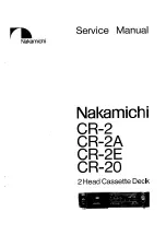
2) Confirm that the B-Y level is A.
Figure 7-5
6. Checking Component Video Output R-Y
<Purpose>
This checks component video output R-Y. If it is incorrect,
correct color will not be displayed when connected to, for instance,
component input projector.
Mode
Video level adjustment in test mode
Signal
Color bars
Test point
COMPONENT VIDEO OUT (CR)
connector, D1 VIDEO OUT
connector, Pin
5
(75
Ω
terminated)
Instrument
Oscilloscope
Specification
B = 700 ± 50 mVp-p (others)
646 ± 50 mVp-p
(For Us, Canada)
Checking method:
1) In the test mode initial menu “6” Video Level Adjustment, set
so that color bars are generated.
2) Confirm that the R-Y level is B.
Figure 7-6
B
A
Summary of Contents for DVP NS725P - Progressive-Scan DVD/CD Player
Page 7: ... 7 6 Set complete Fig 6 ...
Page 8: ... 8 MEMO 8E ...
Page 46: ...2 6 2 10 INTERNAL VIEWS MS128 MOUNT TOPVIEW BOTTOMVIEW Optical Device KHM 290AAA A 6061 908 A ...
Page 48: ...2 8 2 8E ...
Page 88: ...DVP NS325 NS330 NS333 NS430 NS433 NS530 NS725P NS730P 4 59 4 60E ...
Page 112: ...6 22 6 22E ...