5-63
Pattern generator
Video output
(75
Ω
)
Audio
oscillator
Attenuator
600
Ω
600
Ω
(270
Ω
(1-249-410-11) +330
Ω
(1-249-411-11))
Main unit
Main unit
VIDEO
VIDEO
AUDIO
AUDIO
L
R
L
R
In Recording
In Playback
47k
Ω
47k
Ω
:1-249-437-11
Audio level meter or
distortion meter
TV monitor
3-6.
AUDIO SYSTEM ADJUSTMENTS
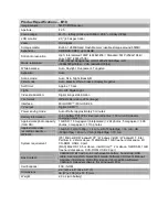
[Connecting the measuring instruments for the audio]
Connect the audio system measuring instruments in addition to the
video system measuring instruments as shown in Fig. 5-3-22.
[Adjustment Procedure]
1)
Hi8/standard 8mm AFM BPF f
0
adjustment
2)
Hi8/standard 8mm AFM 1.5MHz deviation adjustment
3)
Hi8/standard 8mm AFM 1.7MHz deviation adjustment
4)
Digital8 playback level check
5)
Overall level characteristics check
6)
Overall distortion check
7)
Overall noise level check
8)
Overall separation check
Fig. 5-3-22.
1. Hi8/standard 8mm AFM BPF f
0
Adjustment
(VC-213 board)
Sets the BPF passing frequency of IC760 so that the AFM signal
can separate from the playback RF signal properly. If deviated. the
mono/stereo mode will be differentiated incorrectly, and noises and
distortions will increase during high volume playback.
Mode
Playback
Signal
Hi8/standard 8mm alignment tape:
For BPF adjustment
(WR5-11NS (NTSC))
(WR5-11CS (PAL))
Measurement Point
Audio output terminal left or right
Measuring Instrument
Distortion meter
Adjustment Page
F
Adjustment Address\
64
Specified Value
The Main and Sub channel distortion
rate should be almost the same
(within ± 1%) and minimum.
Adjusting method:
1)
Select page: 0, address: 01, and set data: 01.
2)
Set the Hi-Fi sound switch (menu display) to “2”.
3)
Select page: F, address: 64, change the data and minimize the
distortion rate.
4)
Press the PAUSE button of the adjustment remote commander.
5)
Set the Hi-Fi sound switch (menu display) to “1”.
6)
Select page: F, address: 64, change the data and minimize the
distortion rate.
7)
Press the PAUSE button of the adjustment remote commander.
8)
Repeat steps 2) to 7) and set the data of address: 64 so that the
distortions rates when the Hi-Fi sound switch is set to “2” and
set to “1” respectively are almost the same and minimum.
9)
Press the PAUSE button of the adjustment remote commander.
10) Select page: 0, address: 01, and set data: 00.
11) Set the Hi-Fi sound switch to “STEREO”.
Summary of Contents for Digital8 DCR-TRV410
Page 12: ...1 2 ...
Page 13: ...1 3 ...
Page 14: ...1 4 ...
Page 15: ...1 5 ...
Page 16: ...1 6 ...
Page 17: ...1 7 ...
Page 18: ...1 8 ...
Page 19: ...1 9 ...
Page 20: ...1 10 ...
Page 21: ...1 11 ...
Page 22: ...1 12 ...
Page 23: ...1 13 ...
Page 24: ...1 14 ...
Page 25: ...1 15 ...
Page 26: ...1 16 ...
Page 27: ...1 17 ...
Page 28: ...1 18 ...
Page 29: ...1 19 ...
Page 30: ...1 20 ...
Page 31: ...1 21 ...
Page 32: ...1 22 ...
Page 33: ...1 23 ...
Page 34: ...1 24 ...
Page 35: ...1 25 ...
Page 36: ...1 26 ...
Page 37: ...1 27 ...
Page 38: ...1 28 ...
Page 39: ...1 29 ...
Page 40: ...1 30 ...
Page 41: ...1 31 ...
Page 42: ...1 32 ...
Page 43: ...1 33E ...
Page 56: ...DCR TRV410 TRV410E TRV510 TRV510E 3 2 OVERALL BLOCK DIAGRAM 2 3 4 3 5 3 6 ...
Page 58: ...DCR TRV410 TRV410E TRV510 TRV510E 3 10 3 11 3 12E 3 4 POWER BLOCK DIAGRAM 2 ...
Page 79: ...DCR TRV410 TRV410E TRV510 TRV510E 4 73 4 74 STEADY SHOT SE 88 AV IN OUT PJ 97 ...
Page 83: ...DCR TRV410 TRV410E TRV510 TRV510E 4 83 4 84 4 85 USER CONTROL CF 64 ...