


5-45
5. APC & AEQ Adjustment (VC-235 board)
Mode
Camera record and playback
Subject
Arbitrary
Measurement Point
Pin
qh
of CN1108 (RF MON)
(Note 1)
External trigger : Pin
qd
of CN1108
(DV RF SWP)
Measuring Instrument
Oscilloscope
Adjustment Page
C
Adjustment Address
18, 19, 1B, 1C, 21, 2C
Specified Value
The display data of page: 3, address:
03 is “00”
Note 1:
Connect a 75
Ω
resistor between Pin
qh
and Pin
6
(GND)
of CN1108.
75
Ω
resistor (Parts code: 1-247-804-11)
Note 2:
Use a Hi8 MP tape.
Adjusting method:
1)
Select page: 0, address: 01, and set data: 01.
2)
Select page: 8, address: 2A, set data: C8, and press the PAUSE
button of the adjustment remote commander.
3)
Record the camera signal for a minute.
4)
Select page: 2, address: 2E, and set data: 01.
5)
Playback the recorded segment.
6)
Select page: 3, address: 33, and set data: 08.
7)
Confirm that the playback RF signal is stable.
8)
Select page: 3, address: 01, set data: 07, and press the PAUSE
button.
9)
Select page: 3, address: 02, and check that the data changes
from “07” to “00” in about 20 seconds after pressing the PAUSE
button.
10) Select page: 3, address: 03, and check that the data is “00”.
Note 3:
If the data of page: 3, address: 03 is other than “00”,
adjustment has errors.
11) Select page: 3, address: 33, and set data: 00.
12) Select page: 2, address: 2E, and set data: 00.
13) Select page: 8, address: 2A, set data: 00, and press the PAUSE
button.
14) Select page: 0, address: 01, and set data: 00.
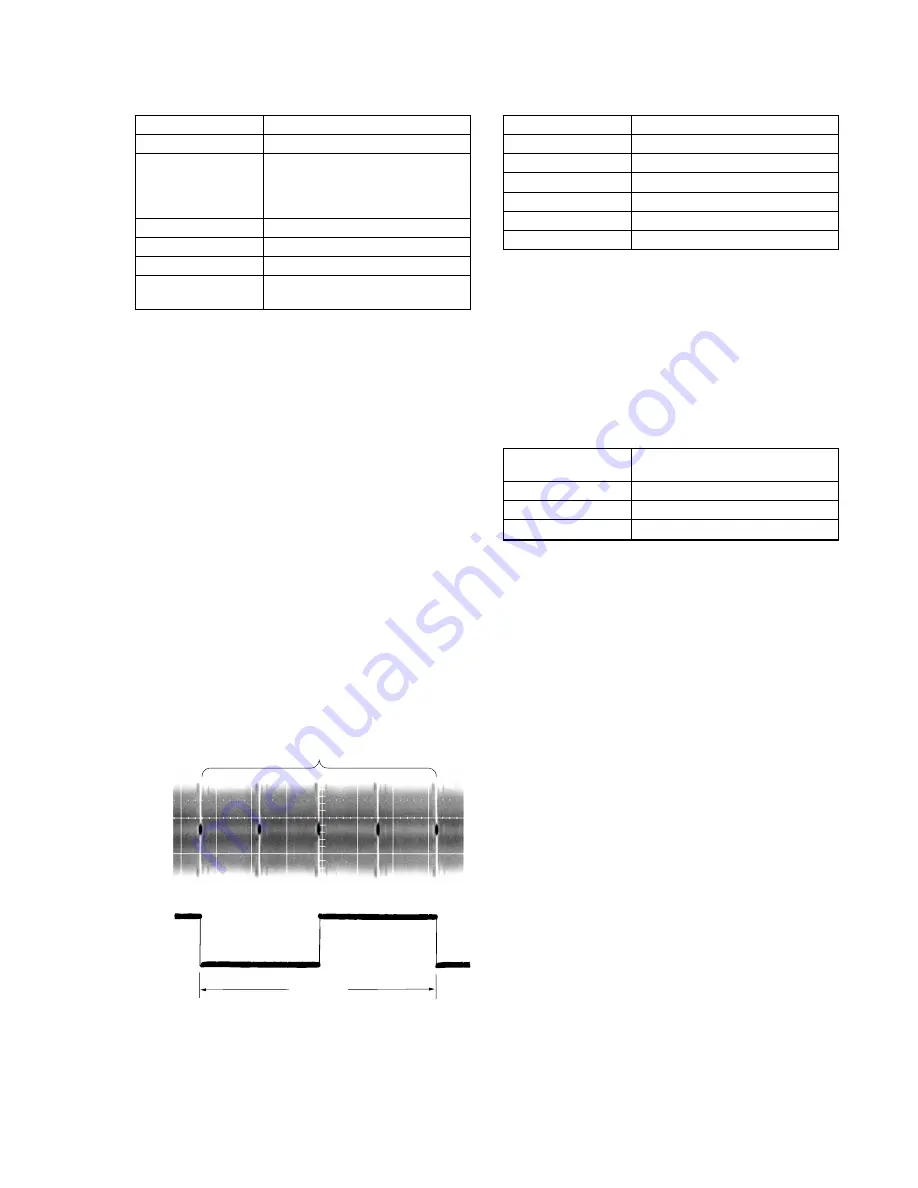
Fig. 5-3-6
6. PLL f
0
& LPF f
0
Final Adjustment (VC-235 board)
Mode
VTR stop
Signal
Arbitrary
Measurement Point
Display data of page: 3, address: 03
Measuring Instrument
Adjustment remote commander
Adjustment Page
C
Adjustment Address
1F, 20, 22, 29
Specified Value
Bit values of bit2, bit3 and bit6 are “0”
Adjusting method:
1)
Select page: 0, address: 01, and set data: 01.
2)
Select page: 3, address: 01, set data: 30, and press the PAUSE
button of the adjustment remote commander.
3)
Select page: 3, address: 02, and check that the data changes to
“00”.
4)
Select page: 3, address: 03, and check that bit values of bit2,
bit3 and bit6 are “0”.
Note:
If bit value of bit 2, bit 3 or bit 6 is “1”, there are errors.
For the error contents, see the following table. (For the
bit values, refer to “5-4. SERVICE MODE”, “4-3. 3.
Bit value discrimination”)
Bit value of page: 3,
Error contents
address: 03
bit 6 = 1
LPF f
0
adjustment is defective
bit 3 = 1
PLL f
0
, fine adjustment is defective
bit 2 = 1
PLL f
0
, fine adjustment is defective
5)
Select page: 0, address: 01, and set data: 00.
13.3 msec
PB RF signal is stable
Pin
qd
Pin
qh
Summary of Contents for DCR-TRV120P
Page 13: ...1 2 ...
Page 14: ...1 3 ...
Page 15: ...1 4 ...
Page 16: ...1 5 ...
Page 17: ...1 6 ...
Page 18: ...1 7 ...
Page 19: ...1 8 ...
Page 20: ...1 9 ...
Page 21: ...1 10 ...
Page 22: ...1 11 ...
Page 23: ...1 12 ...
Page 24: ...1 13 ...
Page 25: ...1 14 ...
Page 26: ...1 15 ...
Page 27: ...1 16 ...
Page 28: ...1 17 ...
Page 29: ...1 18 ...
Page 30: ...1 19 ...
Page 31: ...1 20 ...
Page 32: ...1 21 ...
Page 33: ...1 22 ...
Page 34: ...1 23 ...
Page 35: ...1 24 ...
Page 36: ...1 25 ...
Page 37: ...1 26 ...
Page 38: ...1 27 1 27 E ...
Page 84: ...DCR TRV120 TRV120E TRV120P TRV125E TR8000E TR8100E 4 61 4 62 USER CONTROL CF 69 ...
Page 88: ...DCR TRV120 TRV120E TRV120P TRV125E TR8000E TR8100E 4 69 4 70 USER CONTROL CF 71 ...