Chapter 4:
Setup and Operation
47
To receive your license key, you will need to provide the following information, which is displayed on the system
information screen of your system:
Installing a License Key
When you have obtained a license key for your software, you must enter it into the system. Once a valid license key
has been entered, the system remains licensed until the next time the system software is upgraded.
Table 4.4: Software License Key Information
System Software
Transducer Software
Name of the person installing the upgrade
Name of the person installing the upgrade
Serial number (located on the bottom of your system)
Serial number
ARM version
REF number
PCBA serial number
SH database version
Install
License Key
1
Turn on the system.
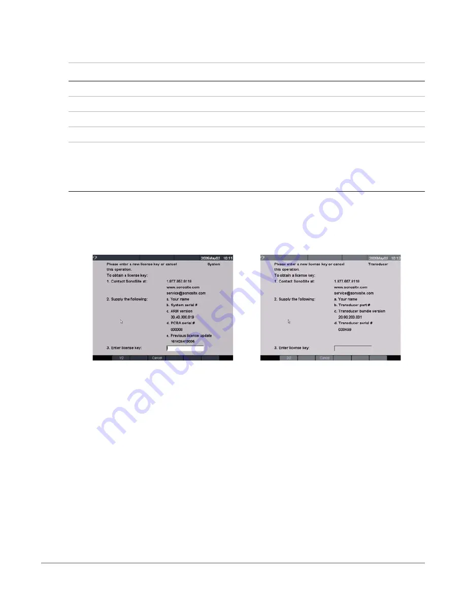
If the software is not yet licensed, the license update screen displays.
The license update screen displays the following information: how to contact SonoSite, the
required information to obtain the license key, and the grace period (time remaining) on your
system.
Figure 4.14 System and Transducer License Screens
2
Enter your license key in the license number field.
3
Select Done from the on-screen menu to install the license key and license your software.
Note: If you have entered a valid license key and you cannot complete the licensing procedure, verify
that the license key has been entered correctly. The license key should be exactly 12 digits (for example,
123348990552) with no other characters or punctuation.
Note: If after confirming correct entry of the license key, you are still unable to license your system, call
SonoSite technical support. USA/Canada customers call
1-877-657-8118
. International customers
call your local representative or
1-425-951-1330
.
Summary of Contents for MicroMaxx
Page 1: ...MicroMaxx Ultrasound System Service Manual ...
Page 6: ...vi ...
Page 10: ...4 Chapter 1 Introduction ...
Page 56: ...50 Chapter 5 Cleaning and Disinfecting ...
Page 61: ...Chapter 6 Troubleshooting 55 Control Panel Figure 6 3 Control Panel Flow Diagram ...
Page 62: ...56 Chapter 6 Troubleshooting System Figure 6 4 System Flow Diagram ...
Page 63: ...Chapter 6 Troubleshooting 57 Battery Figure 6 5 Battery Flow Diagram ...
Page 72: ...66 Chapter 7 Replacement Procedures Figure 7 10 Power Supply Screws Screws 7 ...
Page 85: ...Appendix A Parts List 79 Figure A 1 Power Supply P05471 Figure A 2 Speaker Assembly P03872 ...
Page 89: ...Appendix A Parts List 83 Figure A 8 Main PCB Assembly P05472 ...
Page 92: ...86 Appendix B Service Event Report ...
Page 98: ...92 Index ...


