background image


Chapter 4:

 Setup and Operation

37

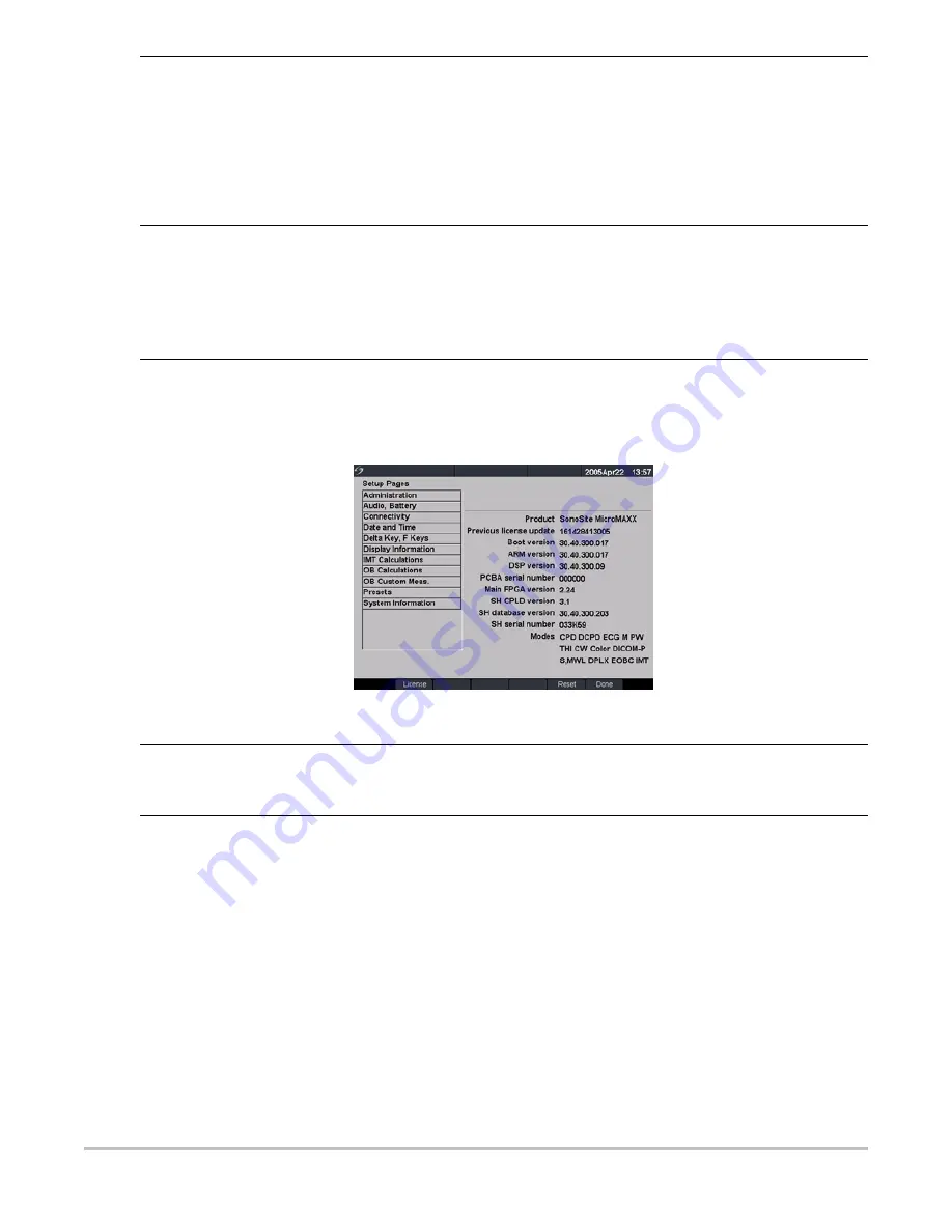
System Information

Figure 19 Setup Screen: System Information

Save Key

1

Press the 

Setup

 key.

2

Select Presets.

3

In the Save key list, select Image Only or Image/Calcs to designate the function 
of the Save key.

• Selecting Image Only allows the 

Save

 key to save the image to the 

CompactFlash card.

• Selecting Image/Calcs allows the 

Save

 Key to save the image to the 

CompactFlash card and to save the current calculation to the report.

Dynamic Range

1

Select the desired exam type.

2

Press the 

Setup

 key.

3

Select Presets.

4

Select the desired dynamic range setting (-3, -2, -1, 0, +1, +2, +3).

Note: Negative numbers show higher contrast images and positive numbers show 
lower contrast images.

Reset

Select Reset from the on-screen menu to return settings for this setup page to 
factory default.

System Information

1

Press the 

Setup

 key.

2

Select System Information from the on-screen menu.

Note: To install a license key see 

“Install License Key” on page 47

.

Change to Default 
Settings

1

Turn the system off.

2

Connect the system to AC power. See 

“Operate System Using AC power” on 

page 40

.

3

Simultaneously press and release 

1

 and the 

Power

 key.

The system beeps several times and then the image display appears with all 
default settings.

Note: Default settings cannot be changed by the user. Default settings are set at 
the factory.

Summary of Contents for MicroMaxx

Page 1: ...MicroMaxx Ultrasound System Service Manual ...

Page 2: ...5207225 5215094 5226420 5226422 5233994 5255682 5275167 5287753 5305756 5353354 5365929 5381795 5386830 5390674 5402793 5 423 220 5438994 5450851 5456257 5471989 5471990 5474073 5476097 5479930 5482045 5482047 5485842 5492134 5517994 5529070 5546946 5555887 5603323 5606972 5617863 5634465 5634466 5636631 5645066 5648942 5669385 5706819 5715823 5718229 5720291 5722412 5752517 5762067 5782769 580035...

Page 3: ...Additional System Feature Performances 15 ECG Module 16 DICOM 17 IMT 17 System Specifications 17 System Dimensions 17 Display Dimensions 17 Transducers 17 Imaging Modes 18 Image Storage 18 Accessories 18 Peripherals 19 Temperature Pressure and Humidity Limits 19 Electrical 19 Battery 19 Electromechanical Safety Standards 20 EMC Standards Classification 20 Airborne Equipment Standards 20 DICOM Stan...

Page 4: ...ng and Disinfecting Universal Precautions 49 Receipt of Suspected Contaminated Materials 49 Recommended Disinfectants 49 Chapter 6 Troubleshooting Basic Troubleshooting 51 Periodic Maintenance 52 System and Subsystem Diagnosis 52 System Repair 52 Test Equipment 53 Failure Assert Codes 53 Verifying a System Assert Code 53 Troubleshooting Flow Diagrams 54 Display 54 Control Panel 55 System 56 Batter...

Page 5: ...ode Imaging 72 Tissue Harmonic Imaging 72 Pulsed Wave PW Doppler Imaging 73 Image Quality Verification Test Livescan 73 Image Review 73 Printer 73 Battery Charging 73 Video Output 74 Returning Products to SonoSite 74 Contacting SonoSite Technical Support 74 Shipping Instructions 74 Appendix A Parts List Replacement Parts List 75 Display 75 Control Panel 77 Replacement Parts System 78 Transducer Ne...

Page 6: ...vi ...

Page 7: ... precautions necessary to prevent injury or loss of life A Caution describes precautions necessary to protect the products When the steps in the operating instructions must be performed in a specific order the steps are numbered Bulleted lists present information in list format but they do not imply a sequence The system handle is on the front of the system and the battery compartment is on the ba...

Page 8: ... exam type Figure 1 1 MicroMaxx System Front View Figure 1 2 MicroMaxx System Rear View Table 1 1 MicroMaxx System Front Features Number Feature 1 Control panel 2 Handle 3 Display 4 CompactFlash slots front for image storage back for system and transducers updates import export OB tables user names passwords and DICOM configurations Table 1 2 MicroMaxx System Rear Connectors Number Feature 1 DC in...

Page 9: ... are covered in the applicable SonoSite accessory user guide About the System Software The ultrasound system contains software that controls its operation A software upgrade may be required for new feature releases Should an upgrade be required SonoSite will provide you with a CompactFlash card containing the software A single CompactFlash card can be used to update one or more systems Software up...

Page 10: ...4 Chapter 1 Introduction ...

Page 11: ...ualified technician To avoid the risk of injury do not operate the system in the presence of flammable gasses or anesthetics Explosion can result To avoid the risk of electrical shock use only properly grounded equipment Shock hazards exist if the power supply is not properly grounded Grounding reliability can only be achieved when equipment is connected to a receptacle marked Hospital Only or Hos...

Page 12: ...IEC Standard 60950 Information Technology Equipment ITE Caution Do not use the system if an error message appears on the image display note the error code call SonoSite or your local representative turn off the system by pressing and holding the power key until the system powers down To avoid increasing the system and transducer connector temperature do not block the airflow to the ventilation hol...

Page 13: ...he battery terminals are fixed and cannot be switched or reversed Do not force the battery into the system Do not connect the battery to an electrical power outlet Do not continue recharging the battery if it does not recharge after two successive six hour charging cycles If the battery leaks or emits an odor remove it from all possible flammable sources Caution To avoid the battery bursting ignit...

Page 14: ...n either within the clinical image or in the area outside of the clinical image Artifacts are indicative of hardware and or software errors that must be corrected before use Some transducer sheaths contain natural rubber latex and talc which can cause allergic reactions in some individuals Refer to 21 CFR 801 437 User labeling for devices that contain natural rubber Perform ultrasound procedures p...

Page 15: ...s image storage and review printing and recording capabilities The system includes the ability to measure the intima media thickness IMT of the carotid artery using digital ultrasound images The IMT measurement of the carotid artery may be used adjunctively with other medical data obtained by a physician to help assess the cardiovascular health of a patient The system includes Digital Imaging and ...

Page 16: ... transducer The beamformer times the transmit pulses to focus the acoustic beam The beamformer amplifies the low level echo signal and times the receive information to focus the receive information The system beamformers up to 64 transmit elements and 64 receive elements The Processing Subsystem includes capabilities for interfacing with the beamformer and performing high speed processing The proc...

Page 17: ...a full circle depending on the particular transducer used 2D mode can be used in combination with any other modes M Mode M Mode is also known as T M mode or time motion mode It is used primarily for cardiac measurements such as valve timing and septal wall thickness when accurate timing information is required Ultrasound echoes of different intensities are mapped to different gray scale values in ...

Page 18: ...ence The 2D image has a graphical line D line superimposed on the 2D image indicating where the M mode beam is located Pulsed Wave PW Doppler PW provides a real time representation of blood flow and is displayed as a velocity versus time sweeping output Velocity or frequency is presented as the vertical axis with time along the horizontal axis The magnitude of the detected signal is represented as...

Page 19: ...Doppler signal as stereo audio The 90 degree phase shift in the in phase component is accomplished by convolving it with the Hilbert Transform impulse response The quadrature component data stream does not undergo any filtering other than a delay that matches the group delay of the in phase channel This is followed by a stage that computes the sum and difference of in phase and quadrature componen...

Page 20: ...ures Tissue motion is discriminated from blood flow by assuming that blood is moving faster than the surrounding tissue although additional parameters may also be used to enhance the discrimination The remaining signal after wall filtering may be averaged over time persistence to present a steady state image of blood flow distribution Variance information may also be displayed to provide informati...

Page 21: ... of biopsy guidelines that represent the anticipated path of the biopsy needle The image of an anatomical target biopsy guidelines a scan plane marker and a biopsy needle are displayed on the monitor to assist in guiding the biopsy needle to the target The system also provides needle guidance for vascular access procedures Additional information regarding this feature can be found in the biopsy us...

Page 22: ...ifier block Isolation block High pass filter block Variable amplifier block Low pass filter block Power supplies block Pre Amplifier The pre amplifier block provides the interface to the ECG leads It provides high levels of common mode rejection and the initial gain for the ECG signal This block also provides a high pass function to eliminate any large direct current DC offsets to allow a moderate...

Page 23: ... in 29 97 cm Width 10 8 in 27 43 cm Height 3 1 in 7 87 cm Weight 8 5 lbs 3 9 kg with the C60e transducer and battery installed Display Dimensions Length 8 4 in 21 34 cm Height 6 3 in 16 cm Diagonal 10 4 in 26 4 cm Transducers C60e 5 2 MHz 60 mm curved array 5 ft 1 5 m HFL38 13 6 MHz 25 mm linear array 5 5 ft 1 7 m ICT 8 5 MHz 11 mm intracavitary array 5 ft 1 5 m L38e 10 5 MHz 38 mm linear array 5 ...

Page 24: ...ftware and Documentation AIUM Ultrasound Medical Safety Guidance Document Battery Biopsy Guide Carry case External display Guidance on the interpretation of TI and MI to be used to inform the operator Annex HH BS EN 60601 2 37 Mobile Docking System Lite MDS Lite Mobile Docking System MDS Mini Dock Power supply Quick Reference Guide SiteLink Image Manager 3 0 SonoCalc IMT System User Guide Triple T...

Page 25: ...its System without Battery 35 65 C 31 149 F 15 95 R H 500 to 1060hPa 0 5 to 1 05 ATM Operating Limits Battery 10 40 C 50 104 F 15 95 R H Shipping Storage Limits Battery 20 60 C 4 140 F 0 95 R H 500 to 1060hPa 0 5 to 1 05 ATM For storage longer than 30 days store at or below room temperature Operating Limits Transducer 10 40 C 50 104 F 15 95 R H Shipping Storage Limits Transducer 35 65 C 31 149 F 1...

Page 26: ...y EMC Standards Classification EN 60601 1 2 2001 European Norm Medical Electrical Equipment General Requirements for Safety Collateral Standard Electromagnetic Compatibility Requirements and Tests CISPR11 2004 International Electrotechnical Commission International Special Committee on Radio Interference Industrial Scientific and Medical ISM Radio Frequency Equipment Electromagnetic Disturbance Ch...

Page 27: ...em on and off 2 Alphanumeric Use to enter text and numbers 3 Annotation Text Turns the keyboard on and off for text entry Picto Turns the pictographs pictograph marker on and off Arrow Displays an arrow that can be moved and rotated within the image area 4 THI Turns Tissue Harmonic Imaging on and off 5 Depth Adjusts the imaging depth for 2D Depth Up Decreases imaging depth Depth Down Increases ima...

Page 28: ... an image to the CompactFlash card and saves measurements calculation to the report when configured in system setup 14 Remappable controls Controls features on the context menu which are adjusted based on the system state 15 Forms Setup Access to the system settings Report Access to the patient report Review Access to the patient list and saved patient images and archive functions Patient Access t...

Page 29: ... Configure for type of Audio alert Sleep delay and Power delay Connectivity Configure Printer Video mode Serial Port and Transfer Mode DICOM or SiteLink DICOM and SiteLink are optional features Date and Time Configure Date and Time functions Delta Key F Keys Configure existing system functionality as a shortcut and create predefined labels for images Display Information Configure information displ...

Page 30: ...rocedures to ensure the integrity and confidentiality of information to protect against any reasonably anticipated threats or hazards to the security or integrity of the information or unauthorized uses or disclosures of the information Administrator Login 1 Press the Setup key 2 Select Administration 3 In Administrator Login type Administrator in the Name field 4 Call SonoSite for the password 1 ...

Page 31: ...haracters a z Numbers 0 9 Note The name and password are case sensitive 3 In Sonographer enter the user s initials to display the information in the patient header and the sonographer field in the Patient Information form Optional 4 In Administration Access click the check box to allow users access to all administration privileges or leave unchecked to restrict access Optional 5 Select Save Modify...

Page 32: ...ames and passwords are copied to the CompactFlash card 5 Remove the CompactFlash card Import User Account 1 Insert the CompactFlash card in the back slot of the system See Installing and Removing the CompactFlash Card on page 39 2 Press the Setup key 3 Select Administration 4 Select Import from the on screen menu A dialog box is displayed 5 After all user names and passwords are imported the syste...

Page 33: ...be opened by a text file application e g Microsoft Word or Notepad The log file is named log txt Clear Event Log 1 Select Clear from the on screen menu 2 Select Yes to delete or No to cancel User Login In User Login enter Name and Password and click OK Guest Login In User Login select Guest In Guest mode the user is able to scan but is restricted from accessing system setup and patient information...

Page 34: ...s the Setup key 2 Select Audio Battery 3 In the Beep alert list select On or Off Sleep Delay 1 Press the Setup key 2 Select Audio Battery 3 In the Sleep delay list select Off 5 or 10 minutes Power Delay 1 Press the Setup key 2 Select Audio Battery 3 In the Power delay list select Off 15 or 30 minutes Reset Select Reset from the on screen menu to return settings for this setup page to factory defau...

Page 35: ... dock MDS to the VCR DVD or PC Note If PC is selected the system allows report data to be sent as ASCII text from the system to a PC Special third party software must be on the PC to acquire view or format the data into a report Check the compatibility of your software with SonoSite technical support Transfer Mode 1 Press the Setup key 2 Select Connectivity 3 In the Transfer Mode list select DICOM...

Page 36: ... return settings for this setup page to factory default WARNING An accurate date and time are critical for accurate obstetrics calculations Verify that the date and time are accurate before each use of the system The system does not automatically adjust for daylight savings time changes Date 1 Press the Setup key 2 Select Date and Time 3 In the Date field enter the current date year month and day ...

Page 37: ... 1 Press the Setup key 2 Select Delta Key F Keys 3 Type desired text Use the Backspace key or Delete key to correct mistakes Reset Select Reset from the on screen menu to return settings for this setup page to factory default Patient Header 1 Press the Setup key 2 Select Display Information 3 Select the desired check boxes to display desired information in the patient header Mode Data 1 Press the ...

Page 38: ...t Select Reset from the on screen menu to return settings for this setup page to factory default IMT Calculations 1 Press the Setup key 2 Select IMT Calculations 3 In the IMT calculations list select the desired labels Selecting a label places the measurement on the Calculation menu and within the report Selecting None removes a label Reset Select Reset from the on screen menu to return settings f...

Page 39: ...t a blank CompactFlash card in the back slot of the system 2 Press the Setup key 3 Select OB Calculations 4 Select Export from the on screen menu All user defined tables and measurements are copied to the CompactFlash card Import 1 Insert the CompactFlash card in the back slot of the system 2 Press the Setup key 3 Select OB Calculations 4 Select Import from the on screen menu 5 After all user defi...

Page 40: ...easurement is displayed in the calculations menu and the OB report Up to five custom measurements may be saved Delete OB Custom Measurement 1 Press the Setup key 2 Select OB Custom Meas 3 In the Custom Measurements list highlight the last measurement 4 Select Delete Last Note If associated tables and report data exist for the measurement they will be removed from the system Tables Select Tables fr...

Page 41: ...stom table data entered by the user View OB Tables 1 Press the Setup key 2 Select OB Custom Meas or OB Calculations 3 Select Tables from the on screen menu 4 Select the desired table Age or Growth and measurement author Create New OB Custom Tables 1 Press the Setup key 2 Select OB Custom Meas or OB Calculations 3 Select Tables from the on screen menu 4 Select the desired table Age or Growth 5 In t...

Page 42: ...elect Tables from the on screen menu 4 Select the desired custom OB table 5 Select Delete from the on screen menu to remove the custom table from the system Doppler Scale 1 Press the Setup key 2 Select Presets 3 In the Doppler Scale list select cm s or kHz Duplex 1 Press the Setup key 2 Select Presets 3 In the Duplex list select desired image display Full 2D Full Trace 1 3 2D 2 3 Trace 1 2 2D 1 2 ...

Page 43: ...red dynamic range setting 3 2 1 0 1 2 3 Note Negative numbers show higher contrast images and positive numbers show lower contrast images Reset Select Reset from the on screen menu to return settings for this setup page to factory default System Information 1 Press the Setup key 2 Select System Information from the on screen menu Note To install a license key see Install License Key on page 47 Cha...

Page 44: ...ttery is being installed for the first time it will need to be charged Figure 4 1 Insert Battery into System Caution Use only the specified SonoSite battery pack For battery safety notes see Battery Safety on page 7 WARNING To avoid injury to the operator and to prevent damage to the ultrasound system inspect the battery for leaks prior to installing Install Battery 1 Disconnect the power supply f...

Page 45: ...n and OB Tables The CompactFlash card is ready to use when the save icon and the image and clip counters are displayed on the screen Caution If the CompactFlash icon and image and clip counters are not displayed in the system status the CompactFlash card may be defective Turn the system off and replace the CompactFlash card The CompactFlash card may be restored if it is formatted on a PC Formattin...

Page 46: ...hand section of the display indicates the current battery level All Battery Indicator segments lit mean the system battery is fully charged Some Battery Indicator segments lit mean the system battery is partially charged When the battery is charging the Battery Indicator segments light sequentially Table 4 3 contains the charging specifications for the system WARNING The equipment shall be connect...

Page 47: ... Turn the latch counterclockwise 6 Press the latch down securing the transducer connector to the system Remove Transducer 1 Pull the latch up and rotate it clockwise 2 Pull the transducer connector away from the system Caution Do not use the system if an error message appears on the display Note the error code and turn off the system Call SonoSite or your local representative Turn System On Off 1 ...

Page 48: ...the transducer that requires a software upgrade is connected the system prompts the user that the transducer requires the upgrade Upgrade System Software 1 Remove any transducer or Triple Transducer Connect from the system 2 Connect the system directly to the power supply or through the MDS mini dock See the SonoSite accessories user guide 3 Insert the CompactFlash card into the back slot The syst...

Page 49: ...system displays the following message Figure 4 6 System Software Installation When the upgrade is completed the system displays the following message Figure 4 7 System Software Step 2 Restart 6 Select Restart When the operating software has been replaced the system presents you with the license update screen so that you may license the software If upgrading a transducer press Cancel from the on sc...

Page 50: ...lling SonoSite Technical Support for your license keys To postpone obtaining a license key press Cancel from the on screen menu Upgrade Transducer Software 1 Turn the system off and remove the CompactFlash card from the back slot 2 Connect the transducer for the upgrade 3 Turn the system on 4 Wait approximately 10 seconds and then insert the upgrade CompactFlash card Note XXX identifies the curren...

Page 51: ...message Figure 4 11 Transducer Software Loading When the upgrade is completed the system displays the following message Figure 4 12 Transducer Software Installation 6 Select Restart When the transducer software has been replaced the system presents you with the license update screen so that you may license the software for your transducer Upgrade all transducers before obtaining license keys Repea...

Page 52: ...Upgrade TTC If the TTC requires an upgrade for the MicroMaxx system the following message is displayed Do you want to upgrade the Triple Transducer Connect now If this message is displayed perform the upgrade Select Yes to accept and No to cancel the upgrade If you select Yes the system presents you with the license update screen so that you may license the software See Obtaining a License Key on ...

Page 53: ...he software is not yet licensed the license update screen displays The license update screen displays the following information how to contact SonoSite the required information to obtain the license key and the grace period time remaining on your system Figure 4 14 System and Transducer License Screens 2 Enter your license key in the license number field 3 Select Done from the on screen menu to in...

Page 54: ...ersion DSP Version PCBA Serial Number PLD CPLD Version SH Database Version and SH Serial Number Note The software versions on your system may vary based on your upgrade and configuration Figure 4 15 System Information Screen DisplayLicense Update Screen 1 Press the Setup key 2 Select System Information from the on screen menu 3 On the lower section of system information screen select the button un...

Page 55: ...exposure Discard any packing materials removed from a package suspected of contamination in a biohazard container Discard any contaminated materials received with the product in an appropriate biohazard container Contaminated materials may include biohazardous waste and sharps Maintain a disinfecting agent in case any work surface is contaminated The recommended agent is 0 5 sodium hypochlorite bl...

Page 56: ...50 Chapter 5 Cleaning and Disinfecting ...

Page 57: ...n System will not power on Check all power connections Perform the following sequence remove DC input connector and battery wait 10 seconds connect DC input or install battery press the power key Ensure the battery is charged System image quality is poor Adjust the LCD screen to improve viewing angle Adjust the brightness as necessary to improve image quality Adjust the gain No CPD image Adjust th...

Page 58: ...cement of parts as recommended by SonoSite in Chapter 7 Replacement Procedures of this manual Component level repair of Printed Circuit Board Assemblies is performed only at the SonoSite repair facility Replacement of board level components by unauthorized service facilities voids the SonoSite warranty Unexpected labels using the function keys Ensure labels have been assigned to the function keys ...

Page 59: ...6 1 Assert Screen Verifying a System Assert Code System asserts are caused by hardware and or software faults Hardware asserts typically require main PCBA replacement Software asserts can be reset and the system may recover A simple method to identify the cause of the assert is identified here Assert code Assert Cause 1 Record the assert code 2 Press the Power button and release it to power the sy...

Page 60: ...54 Chapter 6 Troubleshooting Troubleshooting Flow Diagrams Display Figure 6 2 Display Flow Diagram ...

Page 61: ...Chapter 6 Troubleshooting 55 Control Panel Figure 6 3 Control Panel Flow Diagram ...

Page 62: ...56 Chapter 6 Troubleshooting System Figure 6 4 System Flow Diagram ...

Page 63: ...Chapter 6 Troubleshooting 57 Battery Figure 6 5 Battery Flow Diagram ...

Page 64: ...ing Archiver transaction failed TDICARCH_OPEN_FAILURE Wrong Capture Type Selected Verify that the Archiver supports the selected Capture Type setting E g US Image SC Image or US Ret Image Printer transaction failed TDICPRNT_OPEN_FAILURE Wrong Image Setting Verify that the Printer supports the selected Image settings E g Color RGB or Grayscale Monochrome DICOM network communication failed TDNETWORK...

Page 65: ... mat A wrist grounding strap Display Removal Caution Always use correct ESD procedures ESD damage is cumulative and may not be noticeable at first Initial ESD symptoms may be slightly degraded performance or image quality Display Removal 1 Remove the battery from the system See Section Installing and Removing the Battery on page 38 for battery removal 2 Remove the two screws from the back of the s...

Page 66: ...es Figure 7 2 System Bottom 4 Turn the system over fully open the display and lift off the Control Panel per Figure Figure 7 3 Control Panel Removal 5 Disconnect the two connectors from the display to the Main PCBA per Figure Screws 2 ...

Page 67: ...s Connectors 2 Screws 4 Display Replacement 1 Set the new display in place 2 Install the four screws that hold the Display in place Torque the screws to 5 5 inch pounds 3 Connect the two connectors that connect the Display to the Main PCBA 4 Place the Control Panel in place 5 Reinstall the four screws that hold the Control Panel in place Torque the screws to 5 5 inch pounds ...

Page 68: ...r An anti static mat A wrist grounding strap Control Panel Removal Control Panel Replacement Test Display 1 Replace the battery attach an external power supply or attach a mini dock 2 Press the Power key to apply power to the system 3 Verify the display operates correctly Caution Always use correct ESD procedures ESD damage is cumulative and may not be noticeable at first Initial ESD symptoms may ...

Page 69: ... label Nest Frame Assembly MicroMaxx order these parts individually P00364 Connector Interposer P00524 Screw Shoulder Thrust Plate P00353 Wear Plate P00646 Spring Thrust Plate P02860 Nest Plate Interposer P03834 Shield Perimeter Long P03833 Shield Perimeter Short P02861 Post Mounting Required Tools 1 Phillips screwdriver Torque screwdriver 2 0 10 0 inch pounds 0 23 1 1 newton meter 8 mm nut driver...

Page 70: ...ws 3 Turn the system over and remove the top enclosure from the main PCBA This exposes all of the replaceable parts for the main system per Figure 7 7 Figure 7 7 System Components Screws 4 Nest frame assembly TGC assembly Speaker Speaker Power supply Main PCBA ...

Page 71: ...e Figure 7 8 Figure 7 8 Speaker Replacement Connector Retaining clip Power Supply 1 Gently pry the shield from the power supply and set it aside This part will be used in reassembly Note that the shield fits only one way See Figure 7 9 Figure 7 9 Power Supply Shield 2 Remove the 7 screws that hold down the power supply PCB per Figure 7 10 3 Gently lift the power supply and shield assembly away fro...

Page 72: ...66 Chapter 7 Replacement Procedures Figure 7 10 Power Supply Screws Screws 7 ...

Page 73: ...ure 7 11 TGC Knobs 2 Remove the flex cable from the TGC PCB by lifting on the flex release tab See Figure 7 12 3 Remove the flex cable from the Main PCBA by lifting gently on the flex release tab 4 Remove the two screws holding the TGC PCBA in place Figure 7 12 TGC Removal TGC knobs 3 Release tabs Screws 2 ...

Page 74: ...owing the procedure in Section Figure 7 13 Main PCBA Screws 6 Lift on the edge of the Main PCBA closest to the system handle Note As the Main PCBA is removed press in on the CompactFlash release buttons so they clear the opening in the bottom enclosure Screws 3 Shoulder bolts 4 CompactFlash release buttons Screws 2 Main PCBA Replacement Replace the Main PCBA by following the reverse of the removal...

Page 75: ...he system functions tested in this section could affect safety or effectiveness of the system adversely While performing the steps in this section verify that the images on the system display and on the external monitor are acceptable Set up Performance Tests 1 Attach the C60e 5 2 MHz transducer to the system 2 Select general for optimization and OB for exam type 3 Couple the transducer to the pha...

Page 76: ...s the Freeze key 3 Press the Caliper key The caliper appears on the image display The screen menu indicates Cal 1 Cal 2 and Ellipse If the caliper line setup is on then a dotted line connects the two calipers See the MicroMaxx Ultrasound System User Guide if necessary The Cal 1 caliper is active by default 4 Use the touchpad to position one of the calipers 5 Press the Select key to fix the caliper...

Page 77: ... Freeze key to return the system to live 2D mode Table 8 1 System Measurement Accuracy Measurements Tolerance Axial Distance 2 Lateral Distance 2 Test Penetration 1 Adjust the system controls to obtain a clear image that shows the limits of echo penetration as shown in Table 8 2 2 Measure from the center of the skinline to the deepest vertical position where the scatter echoes start to break up an...

Page 78: ...ing a Doppler phantom Verify that as the gain controls increase and decrease Doppler echo intensity increases and decreases to correspond Verify that no flow exists outside the vessel 2 Save a CPD image by pressing the Freeze key and then the Save key Test M Mode Imaging 1 Attach a C60e transducer and acquire an image 2 Press the M Mode key for the M Mode sample line 3 Position the M Mode sample l...

Page 79: ...pectral trace 4 Place a large drop of ultrasound gel on the transducer lens 5 Gently tap the top of the gel and observe a reflection on the spectral trace and the sound from the speakers 6 Press the 2D key to return to 2D imaging Test Printer Operation 1 Print two images in rapid succession and verify proper operation 2 Verify that the print control on the system functions correctly Test Battery C...

Page 80: ...verifying the video output at the video receptacle Test Video Output 1 Attach an external video monitor to the video connector using the video cable 2 Turn on the system power and verify that the video on the external monitor matches the video on the system display If the video does not appear similar or there is no display on the external monitor see Chapter 6 Troubleshooting for troubleshooting ...

Page 81: ...able parts for the MicroMaxx Ultrasound System All quantities are one unless otherwise noted Display 5 7 6 4 3 2 1 Table A 1 Display Find Number Part Number Description P05463 Service Assembly Display MicroMaxx 1 P02619 Hinge 2 P02172 Wire harness inverter 3 P02173 Wire harness display 4 P05410 Cover screw 5 P04529 Label bezel 6 P04163 Display bezel 7 P04156 Display LCD ...

Page 82: ... shown P02489 Clip display harness P04098 Enclosure back P04345 Display label 3D P04499 Gasket display P04501 Gasket display front P05381 Assembly backlight inverter Table A 1 Display Continued Find Number Part Number Description ...

Page 83: ...Control Panel MicroMaxx English P05465 Service Assembly Control Panel MicroMaxx French P05466 Service Assembly Control Panel MicroMaxx German P05467 Service Assembly Control Panel MicroMaxx Italian P05468 Service Assembly Control Panel MicroMaxx Spanish P05469 Service Assembly Control Panel MicroMaxx Portuguese ...

Page 84: ...osure MicroMaxx Figure A 6 on page 82 P03874 Service Assembly Lower Enclosure MicroMaxx Note This part requires printing a replacement label for the product Contact SonoSite Technical Support when ordering this part to have the label printed and placed on the part 5 P05472 Service Assembly Main PCBA MicroMaxx Note This part does not include the transducer nest frame assembly Those parts must be or...

Page 85: ...Appendix A Parts List 79 Figure A 1 Power Supply P05471 Figure A 2 Speaker Assembly P03872 ...

Page 86: ...80 Appendix A Parts List Figure A 3 TGC Assembly P05470 1 2 3 Table A 4 TGC Assembly Find Number Part Number Description 1 P02317 Assembly PCB TGC 2 P04994 Knob TGC 3 P02308 FFC 12 Position Jumper ...

Page 87: ...Appendix A Parts List 81 Figure A 4 Upper Enclosure P05474 top view Figure A 5 Upper Enclosure Assembly P05474 bottom view ...

Page 88: ...82 Appendix A Parts List Figure A 6 Lower Enclosure P03874 bottom view Figure A 7 Lower Enclosure P03874 top view ...

Page 89: ...Appendix A Parts List 83 Figure A 8 Main PCB Assembly P05472 ...

Page 90: ...n Returning Products to SonoSite on page 74 1 x8 2 x4 4 x4 5 8 x4 3 6 x2 7 x2 Table A 5 Nest Frame Assembly Find Number Part Number Description 1 P00364 Connector Interposer 2 P00524 Screw Shoulder Thrust Plate 3 P00353 Wear Plate 4 P00646 Spring Thrust Plate 047 wire 5 P02860 Nest Plate Interposer 6 P03834 Shield Perimeter Long 7 P03833 Shield Perimeter Short 8 P02861 Post Mounting ...

Page 91: ... it to the following address SonoSite Inc Technical Support 21919 30th Drive SE Bothell Washington 98021 USA Technical Support USA Canada 1 877 657 8118 Technical Support fax 1 425 951 6700 Technical Support e mail service sonosite com SonoSite website www sonosite com and select Support International Technical Support Contact your local representative or call USA 425 951 1330 European Service Cen...

Page 92: ...86 Appendix B Service Event Report ...

Page 93: ...tion Name Ref Number Serial Number Lot Number ARM SHDB Version Configuration Event Description Diagnosis Service Performed Performed By Date Parts Removed Part Name Part Number Serial Number Lot Number Rev Replaced By Parts Installed Part Name Part Number Serial Number Lot Number Rev Replaced By Tests Performed attach test data Test Test Performed By Performed By Result Pass Fail Result Pass Fail ...

Page 94: ...licable the Lot Number from the device identification label ARM SHDB Version the software level of the failed device Typically found on the system information screen Configuration for configurable devices the optional features enabled Typically found on the system information screen as MODES Event Description A description of the problem from the viewpoint of the user Typically what the user repor...

Page 95: ...mbly replacement procedure 62 troubleshooting diagram 55 conventions used 1 D date 30 default settings change to 37 delta key 31 depth description 21 DICOM connectivity 29 display assembly replacement procedure 59 troubleshooting diagram 54 duplex images 36 DVD setup 29 E electrical safety 5 equipment safety 6 error message 6 Ethernet 29 30 event log 26 export user account 26 F F keys 31 fetal age...

Page 96: ...ade 42 SonoSite technical support contact 74 speaker replacement 65 subassembly replacement 52 system charging requirements 40 dimensions 17 information screen 48 measurement accuracy 71 overview 9 software 3 specifications 17 19 troubleshooting diagram 56 turn on off 41 upgrade software 42 wake up 41 system control AC power indicator 22 alphanumeric 21 annotation 21 caliper calcs 22 depth 21 form...

Page 97: ...ducer connect 41 problems 52 remove 41 specifications 17 19 storage and shipping 19 upgrade software 42 U update 22 upgrade system software 42 upgrade transducer software 42 user account 26 user login 25 V VCR problem 51 VCR setup 29 video output tests 74 video recording 22 W warnings 5 Z zoom description 21 ...

Page 98: ...92 Index ...

Reviews: