Sonifex DHY-03, User Handbook Manual
The Sonifex DHY-03 User Handbook Manual is an essential companion for users of this cutting-edge product. With a comprehensive step-by-step guide, this manual enables you to unleash the true potential of the DHY-03. Download the free manual from manualshive.com and explore its numerous features and functionalities effortlessly.
Share
Download


Reviews:
No comments
Related manuals for DHY-03

DSX
Brand: NEC Pages: 32

KX-TVA50
Brand: Panasonic Pages: 72

OP48
Brand: Karel Pages: 13

Slimline 25
Brand: Telstra Pages: 6

55909320
Brand: GE Pages: 100

TRU341 - TRU 341 Cordless Phone
Brand: Uniden Pages: 20

BABYPHONE ROM
Brand: ANSMANN Pages: 38

France oneRoam International Cellular
Brand: Roadpost Pages: 9

J100 Yuva
Brand: Unifone Pages: 18

45SIP
Brand: ESI Pages: 2
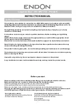
Laughton BLU
Brand: Endon Pages: 2

PA-7262
Brand: Panacom Pages: 16

FWG09
Brand: base engineering Pages: 26

DTC-350
Brand: Daewoo Pages: 24

M4 Social
Brand: Mitsubishi Electric Pages: 102

SPEAK 510
Brand: Jabra Pages: 15

YL-11
Brand: Yolink Pages: 10

440
Brand: Clarity Pages: 100


