1-3
CCU-TX7 (E)/V1
Overview
Product Features
The CCU-TX7/TX7P is a camera control unit that
connects to DXC-637 Series and DXC-D30 Series
Color Video Cameras via the CA-TX7/TX7P Camera
Adaptor.
This product’s features are described below.
Full-featured signal transfer functions
• The CCU-TX7/TX7P is able to transfer wideband
component video signals. (Y signals at 9 MHz or
above, and R–Y and B–Y signals at 4.5 MHz or
above)
• When using a triaxial cable, audio signals can be
transferred up to 750 meters (2460 feet) (when cable
diameter is 8.5 mm (
11
/
32
inch)) or 1,500 meters (4920
feet) (when cable diameter is 14.5 mm (
19
/
32
inch).
• Transfer functions are provided for the following
signals.
Return video, teleprompter signal, microphone audio,
program audio, red tally and green tally signals
• An intercom switch is also provided.
Flexibly adaptable camera control functions
• The optional COU-TX7 Camera Operation Unit,
which can be installed on the CCU-TX7/TX7P’s
front panel, enables video camera operations to be
controlled from the CCU-TX7/TX7P.
• When several CCU-TX7/TX7P units are connected in
parallel, the optional RCP-TX7 Remote Control
Panel can be used to control video camera operations
as well as the color balance between cameras.
• An RS-232C connector is provided for the CCU-
TX7/TX7P, allowing a personal computer to be
connected for computer-based control of video
camera operations.
Wide array of input/output signals
The input and output connectors provided for the
CCU-TX7/TX7P include those for outputting such
signals as a composite video signal (VBS), component
video signals (switchable to RGB), video signals for
video and waveform monitors, and for inputting a
reference signal for external synchronization.
Rack mountable
Two CCU-TX7/TX7P units can be installed side by
side in the optional RMM-TXC7 Rack Mount Bracket.
4
When using one CCU-TX7/TX7P unit
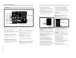
Connections
Examples of how to connect other devices to this unit
are shown in the following.
Notes
• Be sure to power the CCU-TX7/TX7P off before
inserting or removing the triaxial cable connector.
• Some of the video camera’s switches and buttons
may not operate while the CCU-TX7/TX7P is
connected to it.
For details, see the operation manual for the video camera
or camera adaptor.
SYNC
AC IN
WF
PIX
MIC
OUT
RETURN
VIDEO
PROMPT
VIDEO
DC IN
GENLOCK
INTERCOM
CCU/CAMERA
VIDEO
IN
REF
IN
INTERCOM/
TALLY
VBS
VIDEO
IN
CAMERA
REMOTE
Y/R–Y/B–Y,
R/G/B,Y/C
1)
Control console
Out
In
In
In
In/Out
Headset
CA-TX7/TX7P
DXC-D30/D30P
Triaxial cable
CCA-7 cable
RCP-TX7
CCU-TX7/TX7P
3)
(front panel)
Reference sync signal
Teleprompter signal
DC power
source
2)
AC power source
2)
AC power cord
(supplied)
Video monitor
Waveform monitor
1) Y/R–Y/B–Y, R/G/B, and Y/C outputs are switchable.
2) Use either AC or DC power source.
3) This illustration shows the CCU-TX7.
Headset
5


