2-4
CCU-TX7 (E)/V1
2-1-2. Connection Connector
Use the connectors below or the equivalent at its tip when
cables are connected to each connector on the connector
panel during installation and servicing.
Connector name
Connected connector/cable
GENLOCK VIDEO 1, 2
1-560-069-11 plug,
RETURN VIDEO
BNC, or B-B cable assembly
PROMPT VIDEO
(1.5 m in cable length, optional)
R/R-Y/C 1, 2
G/Y/Y 1
B/B-Y 1, 2
WF
PIX
VBS 1/2
SYNC
COAX
(BNC type)
MIC CH1/CH2
1-508-083-00 XLR, 3-pin
RTS
FEMALE or
(3P, MALE)
CANNON XLR-3-11C
or the equivalent
PGM IN
1-508-084-00 XLR, 3-pin
RTS
MALE or
CANNON XLR-3-12C
or the equivalent
INTERCOM/TALLY
D-Sub, 25-pin male,
RS-232C CH1/CH2
JAE DA-25PF-N or the equivalent
(25P, FEMALE)
WF MODE
1-560-343-11 plug, 4-pin male
(4P, FEMALE)
REMOTE
1-766-848-11 plug, 10-pin male, or
(10P, FEMALE)
CCA cable assembly
CCA-7-5 (supplied with RCP-TX7)
(50 m max.)
INTERCOM
1-508-370-11 XLR, 5-pin male,
(5P, FEMALE)
or CANNON XLR-5-12-C or the
equivalent
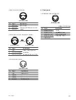
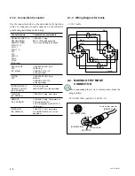
2-1-3. Wiring Diagram for Cable
• CCA-7 cable
2-2. MAKING OF WF MODE
CONNECTOR
• When connecting plug to wave form monitor, make the
plug as follow.
PLUG (4P) (Sony part No. 1-560-343-11)
8
1
5
4
7
9
10
9
10
2
6
3
8
1
5
4
7
2
6
3
Blue
White
White
Brown
Orange
Black
Green
White
Yellow
Red
1
2
4
3
GROUND
STAIR CASE
SEQ CONT
(WIRING SIDE)
To wave form monitor
(REMOTE)
(EXTERNAL VIEW)
4
1
3
2


