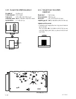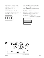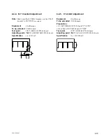
4-24
CCU-TX7 (E)/V1
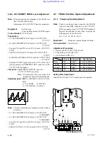
2. Adjust
1
LV2 (PROMPT FREQ)/CT-181 board so that
the frequency response at 6 MHz portion is minimum.
3. Change the output signal of the video signal generator to
10 STEP (sub-carrier : ON) signal.
4. Re-adjust
1
LV3 (PROMPT TUNE)/CT-181 board so that
the “A” portion at video waveform becomes flat.
NOTE : If not met, Re-perform “4-6-2. RX PROMPT
VIDEO Demod. Adjustment” after performing
“4-6-3. RX PROMPT VIDEO RF AGC
Adjustment”.
Note :
After the adjustment is completed, set the switches
as follows.
• S1 (AUX/PROMRT)/YD-25 board (CA-TX7/TX7P)
→
"PROMPT"
• S6 (AUX/PROMRT)/YD-25 board (CA-TX7/TX7P)
→
"PROMPT"
• Connect CN7 and CN3 on the CT-181board. (CCU-TX7/
TX7P)
• S2002 (TX
↔
RX) switch/CT-181 board (CCU-TX7/TX7P)
→
"TX"
6MHz
A
flat
4-6-2. RX PROMPT VIDEO Demod.
Adjustment
Note :
• Perform this adjustment only when replacing
1
LV2
(PROMPT FREQ) or
1
LV3 (PROMPT TUNE)/CT-181
board.
When performing this adjustment, the TRIX cable less than
300 m should be used.
• Adjustment of CA-TX7/TX7P must be completed.
Equipment
:
Waveform monitor,
Video signal generator (10 STEP signal)
To be extended :
CT-181 board
Preparation :
• S1 (AUX/PROMPT)/YD-25 board (CA-TX7/TX7P)
→
"AUX"
• S6 (AUX/PROMPT)/YD-25 board (CA-TX7/TX7P)
→
"AUX"
• Connect CN8 and CN3 on the CT-181board. (CCU-TX7/
TX7P)
• S2002 (TX
↔
RX)/CT-181 board (CCU-TX7/TX7P)
→
"RX"
• S1 (MODE AUTO/MAN)/YD-26 board (CCU-TX7/TX7P)
→
"AUTO"
• Input the SWEEP signal of the video signal generator to
PROMPTER OUT connector on the CA-TX7/TX7P rear
panel.
Test point :
PROMPTER VIDEO IN connector
(CCU-TX7/TX7P rear panel)
Note : To measure the video level, make 75
Z
termination on the waveform monitor side.
Adjusting point :
1
LV2 (PROMPT FREQ)/
CT-181 board
1
LV3 (PROMPT TUNE)/
CT-181 board
Adjustment Procedure :
1. Observe the waveform monitor screen and adjust
1
LV3
(PROMPT TUNE)/CT-181 board so that the video
waveform is appeared.


