4-20
CCU-TX7 (E)/V1
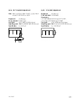
4-4-6. B-Y OUT Level Adjustment
Equipment
:
Oscilloscope
To be extended :
YD-26 board
Preparation :
• S4 (C 2nd AGC)/YD-26 board
→
"ON"
Test point
:
TP17 (GND: E8)/YD-26 board
Adjusting point :
1
RV12 (B-Y LEVEL)/YD-26 board
Specification
:
A = 350
±
5 mV p-p
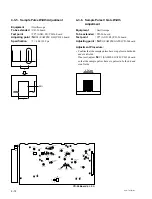
4-4-7. R-Y DEMOD Carrier Balance
Adjustment
Equipment
:
Oscilloscope
To be extended :
YD-26 board
Test point
:
TP18 (GND: E9)/YD-26 board
Adjusting point :
1
RV16 (R-Y CARR BAL)/
YD-26 board
Specification
:
Adjust
1
RV16 so that the negative DC
level is maximum.
A
GND
(Negative DC level) –
Maximum
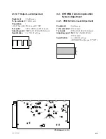
YD-26
YD-26 Board
(A SIDE)
RV1
Y AGC CONT
RV10
C AGC CONT
S2
CABLE LENGTH
S1
RV2
BLACK S/H
RV5
SYNC S/H
RV6
VCO DC SET
RV12
B-Y LEVEL
RV13
OFFSET ADJ
RV14
PLL SET
RV15
C CAR LEV
RV8
SAMPL S/H
RV4
SAMPL GATE
RV3
B-Y CARR BAL
RV11
TP9
TP16
R-Y CARR BAL
RV16
Y LEVEL
RV9
RV17
R-Y LEVEL
RV18
90° SET
S3
Y 2'nd AGC
S4
C 2'nd AGC
LV1
OFF
ON
OFF
ON
MODE
AUTO
MAN
RV24
RV7
Y CAR LEVEL
Y CARR BAL
Y OFFSET ADJ
Y RF TUNE
TP2
E1
E7
E4
TP15
E3
E2
E8
E5
E6
E9
E16
TP3
TP4 TP7
TP6
TP5
TP13
TP1
TP14
TP26
TP10
TP20
TP21
TP12
TP19
TP11
TP18
TP8
TP17


