


Copyright © 2015 Somfy SAS. All rights reserved.
4
EN
CB 230 RTS
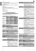
4 - quICk CoMMISSIonIng
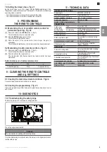
4.1 Memorising the remote controls for operation in
complete opening mode - Fig. 8
It is possible to memorise up to 36 control channels.
If this procedure is carried out using a channel which has already been
memorised, this channel will be cleared.
[1].
Press and hold (2 s) the
PRog
button (7, Fig. 3).
The red indicator will come on permanently.
[2].
Press the button of the remote control that will open the gate fully.
The red indicator light flashes, the remote control has been memorised.
4.2 Checking the motors' direction of rotation
[1].
Switch off the power supply.
[2].
Manually place the gate leaves in the intermediate position and lock the
motors.
[3].
Switch the mains power supply back on.
[4].
Control the gate with a memorised remote control or a control point
connected to the wired control input.
The gate should open.
[5].
If it closes, stop the gate movement, switch on the power supply then
transpose the wires to terminals 5 and 7 or 8 and 10 in the control box.
[6].
Unlock the motors.
[7].
Manually place the gate leaves in the closed position, then lock the
motors.
[8].
Switch the mains power supply back on.
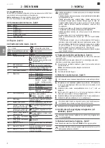
4.3 Programming the gate leaves' travel - Fig. 9
Programming allows the operating time for each motor to be recorded, at normal
speed and when slowing down, and the offset between the two gate leaves.
Programming consists of opening the two gate leaves once. The closing
process will be the same as for opening (same slowdown zone, same offset
between the gate leaves).
Program the gate leaf travel
The gate must be closed and the motors locked to carry out
programming.
If a single gate leaf application has been selected using one
corresponding dipswitch, only the Motor 1 output will be supplied (in
this case, do not carry out step [3]).
[1].
Press the
SEt
button for 2 seconds.
The
PoWER
and
SEt
indicators flash.
[2].
Press the button on a memorised remote control to start programming.
The gate leaf controlled by M1 opens.
[3].
When the required offset between gate leaf M1 and gate leaf M2 has been
reached, press the button on the memorised remote control again.
The gate leaf controlled by M2 opens.
note
: the offset between the two gate leaves can be 0 to 10 seconds.
If no offset is required, press the remote control a second time as soon as
the first gate leaf starts moving.
If no button is pressed within 10 seconds of the first gate leaf starting to
move, the offset between the two gate leaves will be 10 seconds.
[4].
When the gate leaf controlled by M1 reaches the position where a
slowdown is required, press the button on the memorised remote control.
The gate leaf controlled by M1 completes its opening movement at a slower
speed.
The gate leaf controlled by M2 will slow down with the delay programmed
in step [3].
The slowdown phases for the gate leaves will be identical.
note
: Do not complete this step if no slowdown is required.
[5].
When the gate leaves are completely open, wait a few seconds then press
the button on the memorised remote control. The additional seconds will
ensure the gate can open completely if there is a lot of wind or another
type of resistance.
Programming is complete. The POWER indicator is lit steady.
note
: If no slowdown is required, press twice in succession when the gate
leaves are completely open.
During programming, pressing the SET button for 2 seconds will
interrupt programming. During programming, the safety inputs are
active.
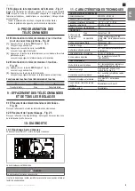
5 - oPERatIng tESt
5.1 using the remote controls - Fig. 10
Default sequential operating mode.
5.2 operation of the photoelectric cells
Cells obscured when closing = the gate stops and reopens fully.
Obstruction of the cells during opening = the gate stops.
5.3 operation of the safety edge
Obstacle detected when opening/closing = stop + partial reversal.
5.4
Specific operation
See the user booklet.
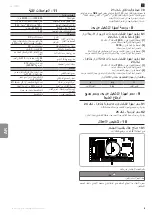
6 - ConnECtIng aDDItIonal DEVICES
6.1 general wiring diagram - Fig. 11
terminals terminal
indication
Connection
Comments
1
2
L
N
230 V power supply
3 - 4
Earth
5 - 6 - 7
M1
Motor 1
Motor which opens
first
8 - 9 - 10
M2
Motor 2
Motor which opens
second
11 - 12
Flash
230V orange light
output
Flashing managed by
the orange light
13 - 14
Pulse
Module for electric
lock
Module to control the
lock
15
16
0 V
24 V
24 V accessories
power supply
315 mA max for all
accessories on all
outputs
17
Test
Safety test output
18
19
Sec Cell - o
Shared
Cell active during
opening
20
Sec Cell - c
Cell active during
closing
8k2 resistive safety
edge
21
ESE
22
Contact
COMPLETE/
OPENING control
input
23
Shared
24
Contact
PEDESTRIAN/
CLOSING control
input
25
26
Conductor
Braid
Aerial
6.2 Description of the various additional devices
Photoelectric cells
•
Wiring to "Cell active during opening input" - Fig. 12
(autotest not available during opening)
•
Wiring to "Cell active during closing input"
-With autotest - DIP SW12 to ON - Fig. 13
-Without autotest - Fig. 14