


3
Copyright © 2015 Somfy SAS. All rights reserved.
EN
CB 230 RTS
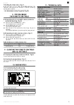
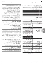
2 - PRoDuCt DESCRIPtIon
2.1 Field of application
The CB 230 RTS control box is designed to control one or two 230V Somfy
motors for opening and closing gates.
number of cycles per hour
: 10 cycles/hour at 20°C, spread uniformly across
the hour (this may vary depending on the type of installation)
2.2 Description of the control box - Fig. 1
no.
Description
1
Cover
2
Cover screw
3
Circuit board
4
Terminal block
5
Spare fuses
2.3 Dimensions - Fig. 2
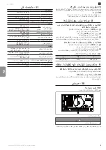
2.4 Description of the circuit board - Fig. 3
Off
Rapid flashing
Slow flashing
Permanently lit
no. Description
Comments
1
POWER indicator
: First time the unit is switched on,
programming not carried out
: Electronic fault (motor thermal cut-
out, etc.)
: Programming complete
2
SET indicator
: Programming in progress
3
SET button
Gate leaf travel programming started/
cleared
4
TIME potentiometer
Setting of the automatic timed close
5
Dipswitches
1 - 2
Motor 1 torque
3 - 4
Motor 2 torque
5
Operation of 1 or 2 motors
6
Gate leaf offset during closing
(for special installation
configurations)
7 - 8 - 9
Operating modes
10
Lock release
11
Orange light warning
12
Cell autotest during closing
6
PROG indicator light
: Radio reception
: Awaiting memorisation of a radio
control point
7
PROG button
Radio control points memorised/cleared
8
Terminal block
Power supply for the control box, motor
wiring and accessories
9
"Cell active during
opening input" indicator
:
Fault or photoelectric cells
obstructed
10
"Cell active during closing
input" indicator
:
Fault or photoelectric cells
obstructed
11
Resistive safety edge
input indicator
: Fault or activation of the safety
edge
12
Total control input
indicator
: Input activated
13
Pedestrian control input
indicator
: Input activated
14
2.5 AT fuse F1
Protection for the 230 V orange light and
the motors
15
100 mAT fuse F2
Surge protection for the 24 V
accessories outputs
16
315 mAT fuse F3
Short circuit protection for the 24 V
accessories outputs
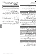
3 - InStallatIon
The electrical connections must be made by a professional electrician.
Check that all national requirements regarding the installation and operation
of electrical appliances are observed.
Any accessible live wires leading out of the electronic unit must be protected
to ensure they cannot be pulled out (using a cable gland with the correct
level of pull-out resistance, for example). Any accessible live wires must
be able to withstand tension of 100 N and torsion of 0.35 Nm. They must
protect the conductor insulation against any abrasion.
This cable gland device must provide sealing to IP44 standard.
All the cables must be fitted in the motorisation from underneath, without
twisting.
It is recommended that rigid or flexible tubes are used for fitting the
electrical cables.
Use a cable with a 1.5 mm² cross section for the power supply cable.
Use cables with a 0.75 mm² cross section for the motor and accessories
wiring.
To prevent any interference, separate the 230V power supply cables from
the low voltage control cables using separate ducts. Keep the 230V power
supply cables together (using a cable tie, for example) and strip them as
close as possible to the connectors (terminals 1 to 12). Do the same for the
24V accessories power supply cables (terminals 13 to 26).
if an extension is necessary for the motor power supply cable, use a cable
recommended for mobile fitting outdoors.
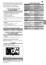
3.1 Securing the control box - Fig. 4
- The maximum authorised length of the cables connecting the control box to
the motors is 20 m.
- Install the control box at least 40 cm above the ground.
-Use suitable screws for the type of mounting bracket.
[1].
Use the base of the control box to trace the mounting points on the
bracket.
attention
: check that the control box is level.
[2].
Drill the bracket.
[3].
Mount the control box.
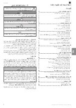
3.2 Wiring the motors - Fig. 5
M1 is the motor installed on the gate leaf which opens first and closes
last.
[1].
Wire the motor of the gate leaf that must open first and close last to
connector M1 (terminals 5, 6 and 7). The shared motor terminal (blue
wire) must be connected to terminal 6.
[2].
Cable one of the capacitors provided with the motors to terminals 5 and 7.
[3].
Wire the second motor to connector M2 (terminals 8, 9 and 10). The
shared motor terminal (blue wire) must be connected to terminal 9.
[4].
Cable the other capacitor provided with the motors to terminals 8 and 10.
[5].
Cable the earth wire for the motors to terminal 4.
A step for verifying the motor wiring and the gate leaf opening direction
is included at the start of the motorisation commissioning procedure
(section 4.2).
[6].
Secure the capacitors at the bottom of the control box with ties.
3.3
Connection of the 8.2 kΩ resistive safety edge
(ref. 9019589) - Fig. 6
For the installation to be compliant, an active safety edge
must
be
installed.
3.4 Connecting to the mains power supply - Fig. 7
When the control box is switched on, the
PoWER
indicator flashes.
The earth wire must always be longer than the live (L) and neutral (N)
wires in case of detachment.


