23
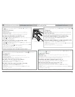
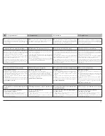
Problèmes
Solutions
Le voyant ON/OFF
ne s’allume pas à
la mise sous
tension.
■
Vérifier l’alimentation secteur
■
Vérifier le câble d’alimentation.
■
Vérifier le fusible.
Le voyant danger
reste allumée
en permanence.
Ce signal indique un défaut cellules. Vérifier :
■
l’alignement des cellules.
■
les câbles des cellules.
■
l’alimentation des cellules.
■
la présence des cellules en mode
automatique.
■
Vérifier s'il n'existe pas une commande
permanente sur les entrées 5 ou 6 de
l'électronique.
Le voyant ON/OFF
clignote
lentement.
■
L’effort demandé à l’Axovia est trop
important. Vérifier que le portail
correspond bien au domaine d’application
donné p.3.
Le voyant ON/OFF
clignote
rapidement.
■
Détection d’un court-circuit sur la sortie
moteur. Refaire le cablage des moteurs
pour éliminer le court circuit.
■
L’électronique est en surchauffe, attendre
5 min avant de générer une nouvelle
commande.
Les vérins M1 et
M2 ne démarrent
pas ou partent
dans le mauvais
sens.
■
Vérifier le raccordement sur l’électronique.
■
Vérifier la rallonge entre les deux vérins.
■
Vérifier le connecteur à câbler (respect
des couleurs de fils).
La portée des
émetteurs est
réduite.
■
Vérifier que la position de l’antenne
d’origine est conforme aux instructions
données p.11.
■
Vérifier la pile émetteurs.
■
Environnement perturbé (pylône
électrique, murs ferraillés, etc.) Prévoir une
antenne extérieure.
■
Pour les véhicules équipés de
climatisation avec pare brise métallisé:
pointer la télécommande sur le bandeau
noir du pare brise ou pointer à travers
l’une des vitres latérales non traitée, ou
émettre vitre ouverte.
A la fin de sa
fermeture, le
portail se ré-ouvre
tout seul.
■
Décaler légèrement la patte de fixation
vantail, sens opposé au gond.
A la fin de l’ou-
verture, le por-tail
se referme tout
seul.
■
Vérifier le câblage des vérins.
12
Problèmes / Solutions
Problem / Causes
Probleem / Mogelijke oorzaak
Problema / Posible Causa
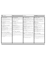
Problem
Cause
ON/OFF does not
go on when power
is supplied.
■
Check mains supply is present.
■
Check the power supply cable is correct.
■
Check the fuse.
Warning stays
on continuously.
This signal indicates a photocell fault.
■
Check the alignment of the photocells.
■
Check the photocell cables are correct.
■
Check the power supply to the photocells.
■
Check the presence of the photocells in
automatic mode.
■
Check whether there is a permanent
command on inputs 5 or 6 on the
electronics.
ON/OFF flashes
slowly
■
The force required by the Axovia is too
great. Check if the gate fits the application
guidelines given on page 3.
ON/OFF flashes
quickly
■
Detection of a short-circuit on motor
output. Rewire the motors to eliminate the
short-circuit.
■
Electronics overheating, wait for 5 min
before generating a new command.
The M1 and M2
motors do not
start or go in the
wrong direction.
■
Check the connections to the electronic
box.
■
Check the extension between the two
motors.
■
Check the cable connector (respect for
wire colours).
The range of the
transmitters is
reduced.
■
Check that the original antenna position
complies with the instructions in p.11.
■
Check the antenna wire.
■
Check the transmitter batteries.
■
Disturbed environment (electric pylon, iron
walls, etc.), provide an external antenna.
■
For vehicles fitted with A/C and a
metallized windshield: target the remote
control on the windshield's black banner
or through one of the normal side
windows or with the window open.
At the end of its
closing, the gate
opens again all by
itself.
■
Offset slightly the leaf attachment lug in
the direction opposite the hinge.
At the end of
opening, the gate
closes all by itself.
■
Check cylinder wiring
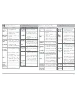
Problema
Posible Causa
ON/OFF no se
enciende al
conectar la
alimentación.
■
Verificar la alimentación del sector.
■
Verificar el cable de alimentación.
■
Verificar el fusible.
se queda
encendido
permanen-
temente
Esta señal indica un defecto de las células
fotoeléctricas.
■
Verificar el alineamiento de las células.
■
Verificar los cables de las células.
■
Verificar la alimentación de las células.
■
Verificar la presencia de las células en
modo automático.
■
Verificar si existe un comando
permanente en las entradas 5 ó 6 de la
electrónica.
ON/OFF parpadea
lentamente
■
El Axovia está sometido a demasiado
esfuerzo. Verificar que la puerta se ajusta
a las características expresadas en la
pag.3.
ON/OFF parpadea
rápidamente
■
Detección de un cortocircuito en la salida
del motor. Volver a realizar el cableado de
los motores para eliminar el cortocircuito.
■
La electrónica está sobrecargada, esperar
5 min antes de generar una nueva orden.
Los operadores
M1 y M2 no se
mueven o lo
hacen en sentido
incorrecto.
■
Verificar la conexión electrónica.
■
Verificar el alargador entre los dos
operadores.
■
Verificar el conector a cablear (respete los
colores de los cables).
Se ha reducido el
alcance de los
emisores.
■
Verificar que la posición de la antena de
origen sea conforme a las instrucciones
proporcionadas en la p.11.
■
Verificar el cable de la antena.
■
Verificar la pila del emisor.
■
Entorno perturbado (pilón electrico,
muros con estructuras de hierro, etc.).
Instale una antena exterior.
n Para los vehículos equipados de
climatización con parabrisas metalizado:
apuntar el mando a distancia sobre la
banda negra del parabrisas o apuntar a
través de uno de los vidrios laterales no
tratados o emitir con el vidrio abierto.
Al terminar el
cierre, el portón
vuelve a abrirse
solo.
■
Apartar un poco la patilla de fijación hoja,
en el sentido opuesto al gozne.
Al terminar la
apertura, el portón
vuelve a cerrarse
solo.
■
Comprobar el cableado de los cilindros.
Probleem
Mogelijke oorzaak
Onder spanning,
gaat ON/OFF niet
aan.
■
Controleer de voeding.
■
Controleer de voedingskabel.
■
Controleer de zekering.
blijft continu
branden
Dit signaal geeft een probleem op gebied van
de fotocellen aan.
■
Controleer de positie van de foto-
elektrische cellen.
■
Controleer de kabels van de foto-
elektrische. cellen.
■
Controleer de voeding van de foto-
elektrische cellen.
■
Controleer de aanwezigheid van foto-
elektrische cellen in automatische stand.
■
Controleer of er geen permanente
besturing bestaat tussen de ingangen 5 of
6 van de elektronica.
ON/OFF knippert
langzaam
■
De gevraagde kracht van de Axovia is te
groot. Controleer of het tuinhek, qua
afmetingen, overeen stemt met de tabel
van het toepassingsgebied, op blz. 3.
ON/OFF knippert
snel
■
Detectie van kortsluiting op de uitgang
van de motor. Bekabeling van de motoren
opnieuw uitvoeren om kortsluiting weg te
nemen.
■
De elektronica wordt oververhit,
5 minuten wachten alvorens een nieuwe
opdracht te geven.
De motoren M1 en
M2 starten niet of
bewegen in de
verkeerde richting.
■
Controleer de bekabeling tussen de
2 motoren.
■
Controleer de connector van de kabels
(respecteer de kleur van de bedrading).
Het zendbereik is
beperkt.
■
Controleer of de stand van de
oorspronkelijke antenne voldoet aan de
instructies van p.11.
■
Controleer de draad van de antenne.
■
Controleer de batterij van de zenders.
■
Controleer de omgeving (elektriciteitspaal,
muur die ijzer bevat, enz.). Voorzie een
externe antenne.
■
Voor voertuigen met airconditioning en een
metallic voorruit: de afstandsbediening op
de zwarte band van de voorruit richten of
door één van de niet behandelde
zijraampjes of met open raam zenden.
Aan het eind van
het sluiten gaat
het toegangshek
weer vanzelf open.
■
Verplaats de bevestigingshaak van de
deur een beetje, van het scharnier af.
Aan het eind van
het openen gaat
het toegangshek
weer vanzelf dicht.
■
Controleer de bekabeling van de cilinders.

