Installation
and
Operation
Manual
(REV
H)
PVI
6500
/
PVI
7500
11
that
the
inverter
be
mounted
on
the
north
or
east
side
of
buildings
or
on
the
northern
side
of
a
ground
mounted
PV
array.
Following
these
guidelines
help
prevent
the
unit
from
limiting
the
power
produced
due
to
an
excessively
high
inverter
temperature.
In
hot
climates,
the
housing
and
heat
sink
can
reach
160
o
F
(70
o
C)
and
must
be
mounted
on
an
appropriate
material
for
this
temperature
as
well
as
one
that
meets
local
codes.
The
inverter
should
not
be
mounted
where
people
are
likely
to
touch
the
case
or
heat
sink
due
to
the
high
potential
temperature.
CAUTION:
Please
follow
these
guidelines:
The
inverter
weighs
approximately
89
lbs
(40.8kg)
(shipping
weight
in
the
box
with
mounting
plate
is
approximately
104
lb).
Be
sure
to
use
a
mounting
method
that
will
safely
hold
this
weight.
The
ambient
temperature
for
the
PVI
6500
must
be
between
–13
o
F
(–25
o
C)
and
+131
o
F
(+55
o
C)
for
continuous,
full
power
operation.
For
the
PVI
7500
the
maximum
allowable
ambient
temperature
is
+122
o
F
(+50
o
C).
The
inverter
will
automatically
reduce
power
or
shut
down
to
protect
itself
if
the
ambient
air
temperature
rises
above
131
o
F
(55
o
C)/
122
o
F
(50
o
C).
Relative
humidity
shall
be
within
0%
and
95%.
Local
and
national
electrical
codes
require
that
the
inverter
be
connected
to
a
dedicated
AC
circuit.
The
code
also
imposes
limitations
on
the
size
of
the
inverter
and
the
manner
in
with
it
is
connected
to
the
utility
grid.
See
local
codes
for
more
information.
The
cooling
air
enters
at
the
bottom
of
the
heat
sink
and
exhausts
at
the
top
of
the
unit.
See
Figure
2.1.1
for
recommended
clearances
for
cooling
air
and
space
around
the
inverter.
If
you
are
installing
the
inverter
in
a
utility
vault
or
electrical
closet,
the
air
circulation
must
be
sufficient
for
heat
dissipation
–
provide
external
ventilation,
to
maintain
an
ambient
condition
of
less
than
131
o
F
(55
o
C)/
122
o
F
(50
o
C)
for
the
PVI
6500
and
PVI
7500.
The
ambient
temperature
should
be
kept
as
low
as
possible.
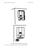
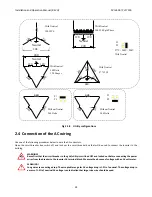
Use
the
dimensional
diagrams
in
Fig.
2.2.1
and
2.2.2,
for
correct
mounting
of
the
inverter.


