Installation
and
Operation
Manual
(REV
H)
PVI
6500
/
PVI
7500
18
2.3
Electrical
Connection
and
Connection
to
the
Grid
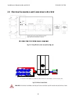
* Colors used in wiring diagram are to differentiate conductors and are not representative of wire colors used pre code.
Fig
2.3.2
Basic
Connections
WARNING:
All
electrical
installations
shall
be
performed
in
accordance
with
local
and
national
electrical
codes.
PVI
6500
‐
7500
PV
SYSTEM
BLOCK
DIAGRAM
Fig.
2.3.1 Simplified
electrical
connection
diagram
* Equipment grounds, grounding electrode conductor
and ground fault detector/interrupter not shown


